БЛОК ДВИГАТЕЛЯ ПОВТОРНАЯ СБОРКА

CAUTION / NOTICE / HINT
Note
-
Always be sure to check the tightening torque.
-
If the pressure lines are leaking after installation, they must be replaced.
-
Do not overtighten the pressure lines.
-
All pressure lines may only be reused 3 times. After the 3rd time, they must be replaced.
PROCEDURE
-
INSTALL NO. 2 OIL NOZZLE SUB-ASSEMBLY
-
Using an E8 "TORX" socket wrench, install the No. 2 oil nozzle sub-assembly with the bolt.
- Torque:
- 10 N*m { 102 kgf*cm, 7 ft.*lbf }
-
-
INSTALL INJECTION PUMP DRIVE GEAR
-
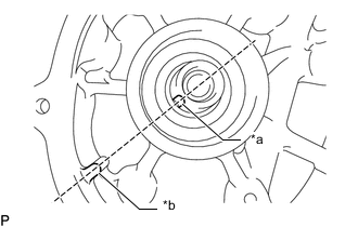
*a Cutout *b Protrusion Align the cutout of the fuel supply pump assembly with the protrusion of the cylinder block and temporarily install the fuel supply pump with the 2 bolts.
-
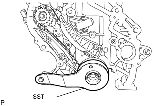
Set the chain sub-assembly to the crankshaft.
-
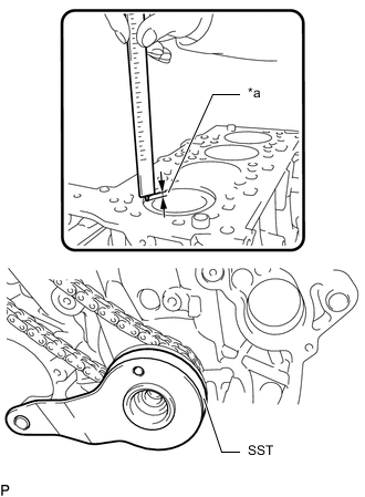
*a 0.5 to 1.0 mm (0.0197 to 0.0394 in.) Install SST by rotating the crankshaft as shown in the illustration.
SST PZ4TB-04964-42 Tech Tips
The No. 1 piston position is 0.5 to 1.0 mm (0.0197 to 0.0394 in.) lower than the top of the cylinder block.
-
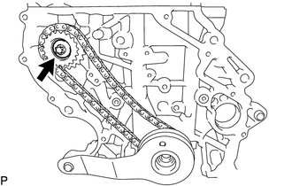
Install the injection pump drive gear with the chain sub-assembly.
-
Install the fuel supply pump assembly with the 2 bolts.
- Torque:
- 19 N*m { 194 kgf*cm, 14 ft.*lbf }
-
Install the central bolt to the injection pump drive gear.
- Torque:
- 65 N*m { 663 kgf*cm, 48 ft.*lbf }
-

Temporarily install the fuel supply pump assembly support with the 4 bolts by hand in the sequence shown in the illustration.
-
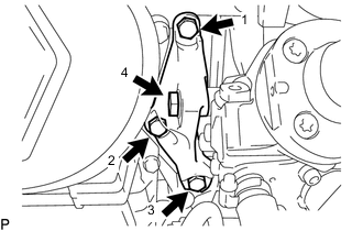
Tighten the 4 bolts in the sequence shown in the illustration.
- Torque:
- 19 N*m { 194 kgf*cm, 14 ft.*lbf }
-
-
INSTALL TIMING CHAIN GUIDE
-
Using a T45 "TORX" socket wrench, install the timing chain guide with the 2 bolts.
- Torque:
- 20 N*m { 204 kgf*cm, 15 ft.*lbf }
-
-
INSTALL TIMING CHAIN TENSION ARM
-
Using a T45 "TORX" socket wrench, install the timing chain tension arm with the bolt.
- Torque:
- 20 N*m { 204 kgf*cm, 15 ft.*lbf }
-
-
INSTALL NO. 1 CHAIN TENSIONER ASSEMBLY
-
Using an E8 "TORX" socket wrench, install the No. 1 chain tensioner assembly with the 2 bolts.
- Torque:
- 10 N*m { 102 kgf*cm, 7 ft.*lbf }
-
Remove the 3.0 mm hexagon wrench from the No. 1 chain tensioner assembly.
-
Remove SST.
SST PZ4TB-04964-42
-
-
INSTALL NO. 2 TIMING CHAIN TENSION ARM
-
Using a T45 "TORX" socket wrench, install the No. 2 timing chain tension arm with the bolt.
- Torque:
- 20 N*m { 204 kgf*cm, 15 ft.*lbf }
-
-
INSTALL NO. 2 CHAIN SUB-ASSEMBLY
-
Install the No. 2 chain sub-assembly to the injection pump drive gear.
-
-
INSTALL OIL PUMP DRIVE CHAIN SUB-ASSEMBLY
-
Install the oil pump drive chain sub-assembly to the crankshaft.
-
-
INSTALL TIMING CHAIN COVER PLATE
-
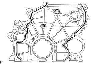
Apply seal packing in a continuous line as shown in the illustration.
Standard Seal Diameter 1.5 to 2.0 mm (0.0591 to 0.0787 in.) Note
-
Remove any oil from the contact surface.
-
Install the timing chain cover plate within 3 minutes of applying seal packing.
-
Do not start the engine for at least 4 hours after installation.
-
-
Using an E8 "TORX" socket wrench, install the timing chain cover plate with the 11 bolts.
- Torque:
- 20 N*m { 204 kgf*cm, 15 ft.*lbf }
-
Apply a light coat of engine oil to a new O-ring, and install it to the sealing cap.
-
Install the sealing cap to the timing case housing.
- Torque:
- 20 N*m { 204 kgf*cm, 15 ft.*lbf }
-
-
INSTALL REAR ENGINE OIL SEAL
-
INSTALL OIL PUMP WITH VACUUM PUMP ASSEMBLY
-
INSTALL OIL STRAINER SUB-ASSEMBLY
-
INSTALL OIL PAN SUB-ASSEMBLY
-
INSTALL FLYWHEEL WITH DAMPER ASSEMBLY
-
INSTALL CLUTCH DISC ASSEMBLY
-
INSTALL CLUTCH COVER ASSEMBLY
-
INSPECT AND ADJUST CLUTCH COVER ASSEMBLY
-
INSTALL TIMING GEAR CASE OR TIMING CHAIN CASE OIL SEAL
-
INSTALL CRANKSHAFT PULLEY
-
SELECT CYLINDER HEAD GASKET
-
INSTALL CYLINDER HEAD GASKET
-
INSTALL CYLINDER HEAD SUB-ASSEMBLY
-
INSPECT VALVE LASH ADJUSTER ASSEMBLY
-
INSTALL VALVE LASH ADJUSTER ASSEMBLY
-
INSTALL NO. 1 VALVE ROCKER ARM SUB-ASSEMBLY
-
INSTALL CAMSHAFT HOUSING SUB-ASSEMBLY
-
SET NO. 1 CYLINDER TO TDC/COMPRESSION
-
INSTALL CAMSHAFT AND NO. 2 CAMSHAFT
-
INSTALL CYLINDER HEAD COVER SUB-ASSEMBLY
-
INSTALL OIL FILLER CAP SUB-ASSEMBLY
-
Install the oil filler cap sub-assembly to the cylinder head cover sub-assembly.
-
-
INSTALL OIL FILTER ASSEMBLY
-
INSTALL OIL FILTER SUB-ASSEMBLY
-
INSTALL WATER OUTLET
-
Install a new gasket to the water outlet.
-
Using an E10 "TORX" socket wrench, install the water outlet with the 3 bolts.
- Torque:
- 10 N*m { 102 kgf*cm, 7 ft.*lbf }
-
-
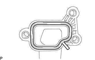
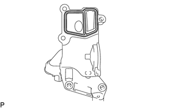
INSTALL WATER INLET HOUSING
-
Apply seal packing in a continuous line as shown in the illustration.
Standard seal diameter 2.0 to 2.5 mm (0.0787 to 0.0984 in.) Note
-
Remove any oil from the contact surface.
-
Install the water inlet housing within 3 minutes of applying seal packing.
-
Do not start the engine for at least 4 hours after installation.
-
-
Using an E11 "TORX" socket wrench, install the water inlet housing with the 5 bolts.
- Torque:
- 20 N*m { 204 kgf*cm, 15 ft.*lbf }
-
-
INSTALL THERMOSTAT
-
INSTALL WATER INLET
-
INSTALL WATER BY-PASS PIPE
-
Using a 5 mm hexagon socket wrench, install the water by-pass pipe to the water inlet housing with the bolt.
Tech Tips
Refer to "SPECIFICATIONS - STANDARD BOLT" for the tightening torque.
-
-
INSTALL ENGINE WATER PUMP ASSEMBLY
-
INSTALL INJECTOR ASSEMBLY
-
INSTALL NOZZLE LEAKAGE PIPE ASSEMBLY
-
INSTALL ENGINE OIL PRESSURE SWITCH ASSEMBLY
-
INSTALL ENGINE COOLANT TEMPERATURE SENSOR
-
INSTALL CRANKSHAFT POSITION SENSOR
-
INSTALL CAMSHAFT POSITION SENSOR