ДВИГАТЕЛЬ В СБОРЕ СНЯТИЕ
CAUTION / NOTICE / HINT
CAUTION:
As the engine assembly with transaxle assembly is extremely heavy, the engine lifter may suddenly drop if the instructions listed in the repair manual are not followed. Therefore, always follow the instructions listed in the repair manual when performing this procedure.
PROCEDURE
-
ALIGN FRONT WHEELS FACING STRAIGHT AHEAD
-
RECOVER REFRIGERANT FROM REFRIGERATION SYSTEM (w/ Air Conditioning System)
-
for HFC-134a(R134a):
-
for HFO-1234yf(R1234yf):
-
-
PRECAUTION
Note
After turning the ignition switch off, waiting time may be required before disconnecting the cable from the battery terminal. Therefore, make sure to read the disconnecting the cable from the battery terminal notice before proceeding with work.
-
DISCONNECT CABLE FROM NEGATIVE BATTERY TERMINAL
Note
When disconnecting the cable, some systems need to be initialized after the cable is reconnected.
-
DISCONNECT CABLE FROM POSITIVE BATTERY TERMINAL
-
REMOVE NO. 1 ENGINE UNDER COVER
-
DRAIN ENGINE COOLANT
-
REMOVE HEADLIGHT ASSEMBLY
-
for Halogen Headlight
-
for LED Headlight
-
-
REMOVE FRONT LOWER BUMPER ABSORBER
-
REMOVE NO. 1 ENGINE COVER
-
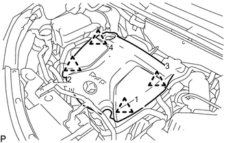
Lift the No. 1 engine cover to detach the 4 clips in the sequence shown in the illustration and remove the No. 1 engine cover.
Note
Attempting to disengage both front and rear clips at the same time may cause the No. 1 engine cover to break.
-
-
REMOVE FRONT FLOOR COVER
-
REMOVE NO. 2 ENGINE UNDER COVER
-
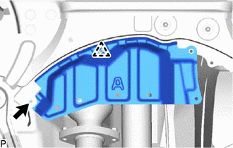
Remove the bolt, clip and No. 2 engine under cover.
-
-
REMOVE FRONT FLOOR COVER RH
-
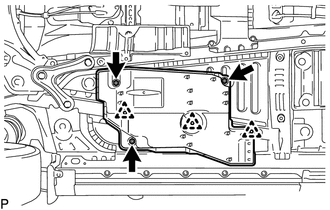
Loosen the 3 nuts and remove the 3 clips and front floor cover RH.
-
-
REMOVE REAR ENGINE UNDER COVER RH
-
REMOVE REAR ENGINE UNDER COVER LH
-
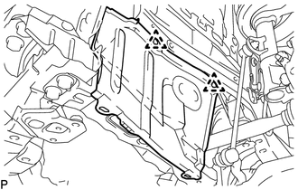
Remove the 2 clips and rear engine under cover LH.
-
-
DRAIN ENGINE OIL
-
DRAIN MANUAL TRANSAXLE OIL
-
REMOVE FRONT EXHAUST PIPE ASSEMBLY
-
REMOVE BATTERY CLAMP SUB-ASSEMBLY
-
REMOVE BATTERY INSULATOR
-
REMOVE BATTERY
-
REMOVE BATTERY TRAY
-
REMOVE BATTERY CARRIER ASSEMBLY
-
REMOVE BATTERY BRACKET REINFORCEMENT
-
REMOVE RADIATOR ASSEMBLY
-
DISCONNECT SUCTION HOSE SUB-ASSEMBLY (w/ Air Conditioning System)
-
DISCONNECT DISCHARGE HOSE SUB-ASSEMBLY (w/ Air Conditioning System)
-
REMOVE AIR CLEANER CAP SUB-ASSEMBLY WITH AIR CLEANER HOSE ASSEMBLY
-
REMOVE AIR CLEANER CASE SUB-ASSEMBLY
-
REMOVE RADIATOR RESERVOIR ASSEMBLY
-
Slide the clamp and disconnect the water by-pass hose assembly from the radiator reservoir assembly.
-
Slide the clamp and disconnect the No. 2 water by-pass hose assembly from the radiator reservoir assembly.
-
Remove the 2 bolts and radiator reservoir assembly.
-
-
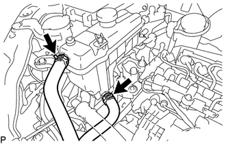
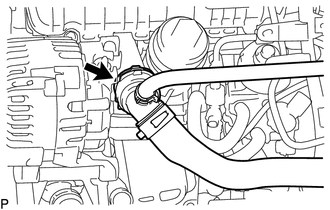
REMOVE WATER BY-PASS HOSE ASSEMBLY
-
Slide the clamp and disconnect the water by-pass hose assembly from the No. 1 air tube assembly.
-
Remove the water by-pass hose assembly from the water by-pass pipe.
-
-
REMOVE RADIATOR HOSE SUB-ASSEMBLY
-
Slide the clamp and disconnect the radiator hose sub-assembly from the No. 1 air tube assembly.
-
Remove the radiator hose sub-assembly from the water outlet.
-
-
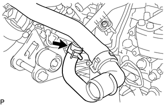
DISCONNECT VACUUM HOSE
-
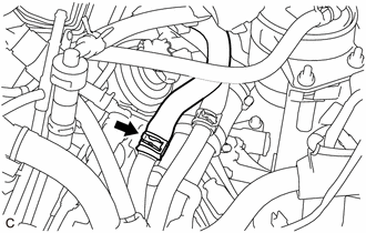
Slide the clamp and disconnect the vacuum hose from the No. 2 vacuum hose assembly.
-
-
DISCONNECT NO. 2 FUEL HOSE
-
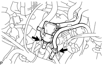
Disconnect the No. 2 fuel hose from the fuel feed pipe sub-assembly.
-
-
DISCONNECT FUEL HOSE
-
Disconnect the fuel hose from the fuel feed pipe sub-assembly.
-
-
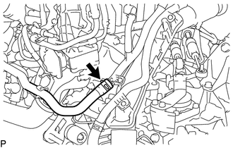
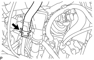
DISCONNECT WATER HOSE SUB-ASSEMBLY
-
Slide the clamp and disconnect the water hose sub-assembly from the No. 1 air tube assembly.
-
-
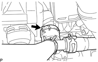
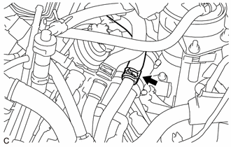
DISCONNECT OUTLET HEATER WATER HOSE
-
Slide the clamp and disconnect the outlet heater water hose from the No. 1 air tube assembly.
-
-
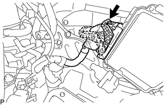
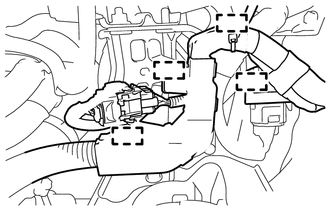
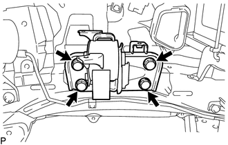
DISCONNECT ENGINE WIRE
-
Remove the No. 1 engine room relay block cover.
-
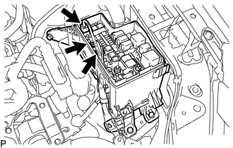
Disconnect the 3 connectors.
-
Remove the nut.
-
Detach the 2 claws to disconnect the engine wire from the No. 1 engine room relay block.
-
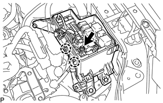
Remove the bolt to disconnect the ground cable.
-
-
REMOVE FUEL FILTER ASSEMBLY
-
REMOVE GLOW PLUG RELAY ASSEMBLY
-
Disengage the glow plug relay assembly from the ECM bracket.
-
-
REMOVE FUEL FILTER SUPPORT
-
Raise the lever while pushing the lock on the lever, and disconnect the ECM connector.
Note
After disconnecting the ECM connector, make sure that dirt, water or other foreign matter does not contact the connecting parts of the ECM connector.
-
Disconnect the connector.
-
Detach the 4 clamps to disconnect the engine wire.
-
Detach the clamp to disconnect the wire harness.
-
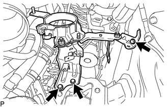
Remove the 3 bolts and fuel filter support.
-
Remove the nut and fuel filter support stay.
-
-
REMOVE AIR CLEANER BRACKET
-
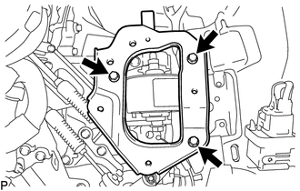
Remove the 3 bolts and air cleaner bracket.
-
-
DISCONNECT TRANSMISSION CONTROL CABLE ASSEMBLY
-
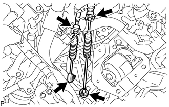
Remove the 2 pins and disconnect the 2 transmission control cable assemblies from the manual transaxle assembly.
-
Remove the 2 clips and disconnect the 2 transmission control cable assemblies from the transmission control cable bracket.
-
-
DISCONNECT CLUTCH RELEASE CYLINDER ASSEMBLY
-
SECURE STEERING WHEEL
-
REMOVE COLUMN HOLE COVER SILENCER SHEET
-
SEPARATE NO. 2 STEERING INTERMEDIATE SHAFT ASSEMBLY
-
REMOVE NO. 1 STEERING COLUMN HOLE COVER SUB-ASSEMBLY
-
REMOVE FRONT DRIVE SHAFT ASSEMBLY
-
REMOVE FRONT ENGINE MOUNTING BRACKET LOWER REINFORCEMENT
-
REMOVE FRONT SUSPENSION MEMBER REINFORCEMENT LH
-
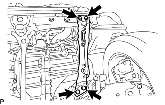
Remove the 2 bolts and front suspension member reinforcement LH.
-
-
REMOVE FRONT SUSPENSION MEMBER REINFORCEMENT RH
-
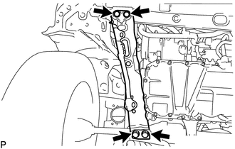
Remove the 2 bolts and front suspension member reinforcement RH.
-
-
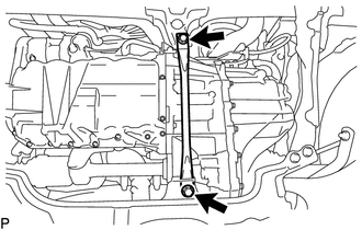
REMOVE FRONT SUSPENSION MEMBER REAR BRACE LH
-
REMOVE FRONT SUSPENSION MEMBER REAR BRACE RH
Tech Tips
Perform the same procedure as for the LH side.
-
REMOVE FRONT SUSPENSION CROSSMEMBER SUB-ASSEMBLY
-
Remove the 2 bolts and front suspension crossmember sub-assembly.
-
-
REMOVE ENGINE ASSEMBLY WITH TRANSAXLE
-
Set an engine lifter.
Note
-
Place height adjustment attachments and plate lift attachments under the engine assembly with transaxle.
-
Do not position the height adjustment attachments or plate lift attachments under the front crossmember sub-assembly.
-
Do not perform any procedure while the engine assembly is suspended because doing so may cause the engine assembly to drop, resulting in injury. However, the engine assembly needs to be suspended when it is installed to or removed from an engine stand.
-
-
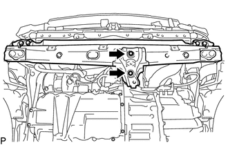
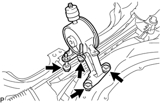
Remove the 2 bolts to disconnect the front engine mounting insulator from the front crossmember sub-assembly.
-
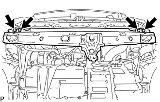
Remove the 4 bolts and front crossmember sub-assembly.
-
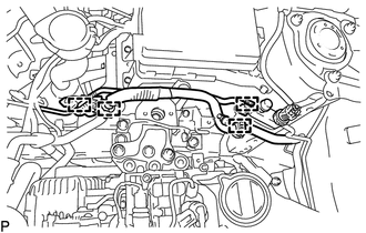
Detach the 2 clamps and disconnect the air conditioner tube and accessory assembly.
-
Detach the 2 clamps and disconnect the suction pipe sub-assembly.
-
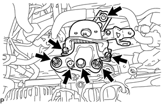
Remove the 4 bolts, 3 nuts and engine mounting insulator sub-assembly RH.
-
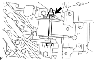
Remove the bolt and nut to remove the engine mounting insulator LH.
Tech Tips
While holding the bolt in place, loosen the nut.
-
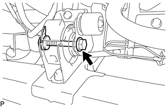
Remove the bolt, nut and disconnect the front engine mounting insulator.
Tech Tips
When removing the bolt, keep the nut from rotating.
-
Carefully remove the engine assembly with transaxle from the vehicle.
Note
Make sure that the engine assembly with transaxle is clear of all wiring and hoses.
-
Using an engine sling device and engine lift, secure the engine assembly with transaxle.
Note
-
Pay attention to the angle of the sling device as the engine assembly or No. 1 engine hanger and No. 2 engine hanger may be damaged or deformed if the angle is incorrect.
-
Do not perform any procedures while the engine assembly is suspended because doing so may cause the engine assembly to drop, resulting in injury. However, the engine assembly needs to be suspended when it is installed to or removed from an engine stand.
-
-
-
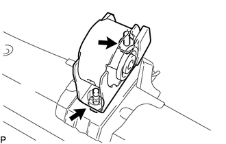
DISCONNECT REAR ENGINE MOUNTING INSULATOR
-
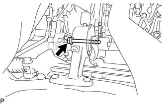
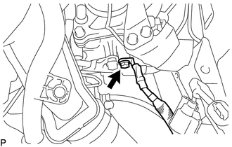
Remove the bolt to disconnect the rear engine mounting insulator.
-
-
REMOVE ENGINE WIRE
-
Disconnect the connectors and detach the clamps securing the engine wire to the engine assembly, and then remove the bracket bolts and engine wire from the engine assembly.
-
-
REMOVE NO. 1 AIR TUBE ASSEMBLY
-
Disconnect the compressor outlet elbow to the turbocharger sub-assembly.
-
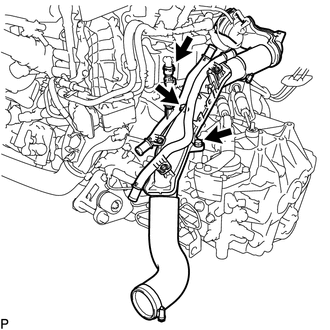
Disconnect the No. 4 water by-pass hose from the EGR cooler assembly.
-
Remove the 2 bolts and disconnect the No. 1 air tube assembly from the manual transaxle assembly.
-
-
REMOVE NO. 1 CLUTCH HOUSING COVER
-
REMOVE NO. 2 MANIFOLD STAY
-
REMOVE STARTER ASSEMBLY
-
REMOVE FRONT ENGINE MOUNTING BRACKET
-
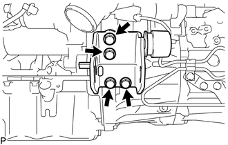
Remove the 4 bolts and front engine mounting bracket from the manual transaxle assembly.
-
-
REMOVE REAR ENGINE MOUNTING BRACKET
-
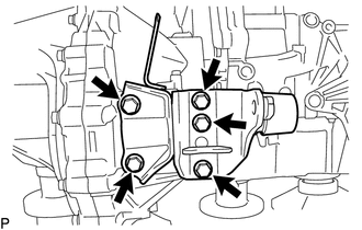
Remove the 5 bolts and rear engine mounting bracket from the manual transaxle assembly.
-
-
REMOVE ENGINE MOUNTING BRACKET LH
-
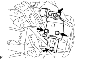
Remove the 4 bolts and engine mounting bracket LH from the manual transaxle assembly.
-
-
REMOVE MANUAL TRANSAXLE ASSEMBLY
-
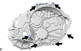
Remove the 6 bolts and manual transaxle assembly from the engine assembly.
-
-
INSTALL ENGINE TO ENGINE STAND
Note
-
Pay attention to the angle of the sling device as the engine assembly or engine hangers may be damaged or deformed if the angle is incorrect.
-
With the exception of installing the engine assembly to an engine stand or removing the engine assembly from an engine stand, do not perform any work on the engine assembly while it is suspended, as doing so is dangerous.
-
Install the engine assembly to an engine stand, and remove the sling device and chain block from the engine assembly.
-
-
REMOVE FRONT ENGINE MOUNTING INSULATOR
-
Remove the 2 bolts and front engine mounting insulator from the front crossmember sub-assembly.
-
-
REMOVE REAR ENGINE MOUNTING INSULATOR
-
Remove the 2 bolts, 2 nuts and rear engine mounting insulator from the front suspension crossmember sub-assembly.
-
-
REMOVE ENGINE MOUNTING INSULATOR LH
Tech Tips
Perform this procedure only when replacement of the engine mounting insulator LH is necessary.
-
Remove the 4 bolts and engine mounting insulator LH from the vehicle body.
-