БЛОК ЦИЛИНДРОВ РАЗБОРКА
PROCEDURE
-
INSPECT CONNECTING ROD THRUST CLEARANCE
-
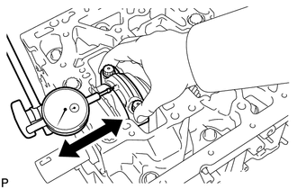
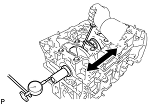
Using a dial indicator, measure the thrust clearance while moving the connecting rod back and forth.
Standard thrust clearance 0.10 to 0.45 mm (0.00394 to 0.0177 in.) Maximum thrust clearance 0.55 mm (0.0217 in.) If the thrust clearance is more than the maximum, replace one or more connecting rod sub-assemblies as necessary. If necessary, replace the crankshaft.
-
-
INSPECT CONNECTING ROD OIL CLEARANCE
-
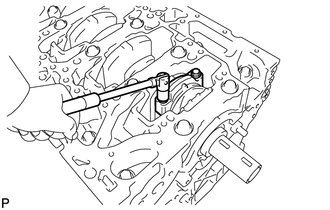
Remove the 2 connecting rod cap bolts.
-
Using the 2 removed connecting rod cap bolts, remove the connecting rod cap and connecting rod bearing by wiggling the connecting rod cap right and left.
Tech Tips
Keep the connecting rod bearing inserted in the connecting rod cap.
-
Clean the crank pin and connecting rod bearing.
-
Check the crank pin and connecting rod bearing for pitting and scratches.
-
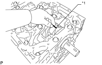
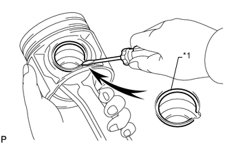
*1 Plastigage Lay a strip of Plastigage on the crank pin.
-
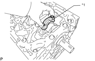
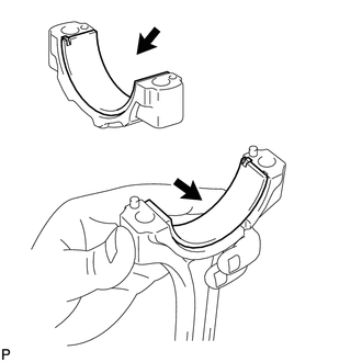
*1 Front Mark Check that the front mark (protrusion) of the connecting rod cap is facing forward and install the cap.
-
Install and alternately tighten the bolts of the connecting rod cap in several steps.
- Torque:
- 40 N*m { 408 kgf*cm, 30 ft.*lbf }
Note
Do not turn the crankshaft.
-
Mark the front side of each connecting cap bolt with paint.
-
Tighten the cap bolts by 90°.
-
Check that the painted marks are now at a 90° angle to the front.
-
Remove the 2 connecting rod cap bolts and connecting rod cap.
Tech Tips
Keep the connecting rod bearing inserted in the connecting rod cap.
-
Measure the Plastigage at its widest point.
Standard oil clearance 0.024 to 0.042 mm (0.000945 to 0.00165 in.) Maximum oil clearance 0.070 mm (0.00276 in.) If the oil clearance is more than the maximum, replace the connecting rod bearings. If necessary, replace the crankshaft.
Tech Tips
If using a standard connecting rod bearing, replace it with one that has the same number. If the number of the connecting rod bearing cannot be determined, select the correct bearing by adding together the numbers imprinted on the crankshaft and connecting rod sub-assembly, and then selecting the connecting rod bearing with the same number as the total. There are 5 sizes of standard connecting rod bearings, marked 1, 2, 3, 4 and 5.
Standard Bearing Chart Item Number Mark Connecting rod cap 3 2 3 1 2 3 1 2 1 Crankshaft 2 2 1 2 1 0 1 0 0 Use bearing 5 4 3 2 1 EXAMPLE:
Connecting rod cap "3" + Crankshaft "1" = Total number 4 (Use bearing "4")
Reference Standard Connecting Rod Big End Inside Diameter Item Specified Condition Mark 1 53.000 to 53.006 mm (2.0866 to 2.0869 in.) Mark 2 53.006 to 53.012 mm (2.0869 to 2.0871 in.) Mark 3 53.012 to 53.018 mm (2.0871 to 2.0873 in.) Standard Crankshaft Pin Diameter Item Specified Condition Mark 0 49.994 to 50.000 mm (1.9683 to 1.9685 in.) Mark 1 49.988 to 49.994 mm (1.9680 to 1.9683 in.) Mark 2 49.982 to 49.988 mm (1.9678 to 1.9680 in.) Standard Sized Bearing Center Wall Thickness Item Specified Condition Mark 1 1.485 to 1.488 mm (0.0585 to 0.0586 in.) Mark 2 1.488 to 1.491 mm (0.0586 to 0.0587 in.) Mark 3 1.491 to 1.494 mm (0.0587 to 0.0588 in.) Mark 4 1.494 to 1.497 mm (0.0588 to 0.0589 in.) Mark 5 1.497 to 1.500 mm (0.0589 to 0.0591 in.) 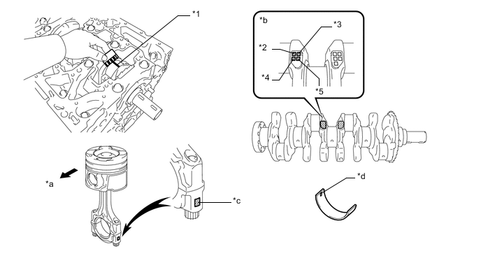
*1 Plastigage *2 No. 1 *3 No. 2 *4 No. 3 *5 No. 4 - - *a Front *b Crankshaft pin diameter: Mark 0, 1 or 2 *c Connecting rod big end inside diameter: Mark 1, 2 or 3 *d Connecting rod bearing: Mark 1, 2, 3, 4 or 5 -
Completely remove the Plastigage.
-
-
REMOVE PISTON SUB-ASSEMBLY WITH CONNECTING ROD
-
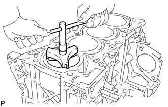
Using a ridge reamer, remove all the carbon from the top of the cylinder.
-
Push out the piston and connecting rod with connecting rod bearing through the top of the cylinder block sub-assembly to remove them.
Tech Tips
Arrange the piston and connecting rod assemblies in the correct order.
-
-
REMOVE CONNECTING ROD BEARING
-
Remove the connecting rod bearings from the connecting rod and connecting rod cap.
Tech Tips
Arrange the removed parts in the correct order.
-
-
REMOVE PISTON RING SET
Tech Tips
Arrange the piston rings in the correct order.
-
Using a piston ring expander, remove the No. 1 compression ring and No. 2 compression ring.
-
Using a piston ring expander, remove the oil ring rail.
-
Remove the oil ring expander by hand.
-
-
REMOVE PISTON WITH PIN SUB-ASSEMBLY
-
Check the fitting condition between the piston and piston pin by trying to move the piston back and forth on the piston pin.
If any movement is felt, replace the piston with pin sub-assembly.
-
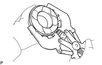
*1 Snap Ring Using a screwdriver, pry out the 2 snap rings.
-
Gradually heat the piston with pin sub-assembly to 80 to 90°C (176 to 194°F).
-
Using a brass bar and plastic-faced hammer, lightly tap out the piston pin and remove the connecting rod.
Tech Tips
-
The piston and pin are a matched set.
-
Arrange the pistons, pins, rings, connecting rods and bearings in the correct order.
-
-
-
INSPECT CRANKSHAFT THRUST CLEARANCE
-
Using a dial indicator, measure the crankshaft thrust clearance while prying the crankshaft back and forth with a screwdriver.
Standard thrust clearance 0.04 to 0.24 mm (0.00157 to 0.00945 in.) Maximum thrust clearance 0.30 mm (0.0118 in.) If the thrust clearance is more than the maximum, replace the upper crankshaft thrust washer. If necessary, replace the crankshaft.
Standard thrust washer thickness 1.93 to 1.98 mm (0.0760 to 0.0780 in.)
-
-
REMOVE CRANKSHAFT
-
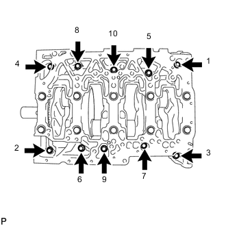
Uniformly loosen and remove the 10 bolts in several steps in the sequence shown in the illustration.
-
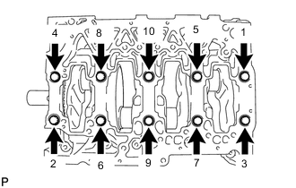
Uniformly loosen and remove the 10 bearing cap bolts in several steps in the sequence shown in the illustration.
-
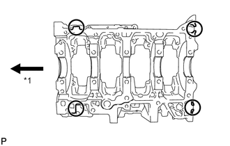
*1 Front Remove the crankshaft bearing cap by prying between the crankshaft bearing cap and cylinder block sub-assembly with a screwdriver.
Note
Do not damage the contact surfaces of the cylinder block sub-assembly and crankshaft bearing cap.
Tech Tips
-
Keep the No. 2 crankshaft bearings and crankshaft bearing caps together.
-
Arrange the upper crankshaft thrust washers in the correct order.
-
Keep the crankshaft bearings and upper crankshaft thrust washers together with the cylinder block sub-assembly.
-
Tape the screwdriver tip before use.
-
-
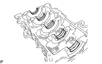
Remove the crankshaft.
-
-
REMOVE UPPER CRANKSHAFT THRUST WASHER
-

Remove the 2 upper crankshaft thrust washers from the cylinder block sub-assembly.
Tech Tips
Arrange the upper crankshaft thrust washers in the correct order.
-
-
REMOVE CRANKSHAFT BEARING
Tech Tips
-
Keep the crankshaft bearing and No. 2 crankshaft bearing and crankshaft bearing cap as a set.
-
Arrange the crankshaft bearing cap and crankshaft bearings in the correct order.
-
Remove the 5 crankshaft bearings.
-
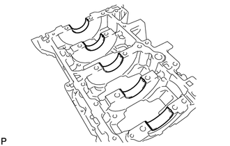
Remove the 5 No. 2 crankshaft bearings.
-
-
REMOVE NO. 1 CRANKSHAFT POSITION SENSOR PLATE
-
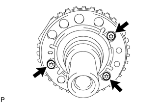
Using a T30 "TORX" socket wrench, remove the 3 bolts and No. 1 crankshaft position sensor plate.
-
-
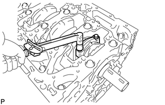
REMOVE NO. 1 OIL NOZZLE SUB-ASSEMBLY
-
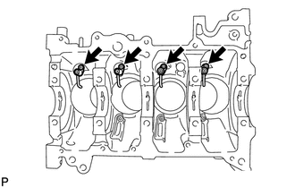
Using a 5 mm hexagon wrench, remove the 4 bolts and 4 No. 1 oil nozzle sub-assemblies.
-
-
REMOVE OIL REFLECTOR PLATE
-
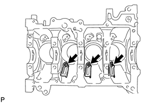
Using a 5 mm hexagon wrench, remove the 3 oil reflector plates.
-
-
REMOVE CYLINDER BLOCK STUD BOLT
Tech Tips
If a cylinder block stud bolt is deformed or the threads are damaged, replace it.