МАСЛЯНЫЙ РАДИАТОР ДВИГАТЕЛЯ СНЯТИЕ
CAUTION / NOTICE / HINT
Note
-
When replacing the injectors (including shuffling the injectors between the cylinders), common rail, intake manifold or cylinder head, it is necessary to replace the injection pipes with new ones.
-
When replacing the fuel supply pump, common rail, intake manifold or cylinder head, it is necessary to replace the fuel inlet pipe with a new one.
PROCEDURE
-
PRECAUTION
Note
After turning the ignition switch off, waiting time may be required before disconnecting the cable from the battery terminal. Therefore, make sure to read the disconnecting the cable from the battery terminal notice before proceeding with work.
-
DISCONNECT CABLE FROM NEGATIVE BATTERY TERMINAL
Note
When disconnecting the cable, some systems need to be initialized after the cable is reconnected.
-
REMOVE DIESEL THROTTLE BODY ASSEMBLY
-
DRAIN ENGINE OIL
-
DISCONNECT ENGINE WIRE
-
REMOVE EGR VALVE BRACKET
-
REMOVE NO. 7 WATER BY-PASS HOSE
-
DISCONNECT NO. 8 WATER BY-PASS HOSE
-
REMOVE NO. 2 EGR PIPE SUB-ASSEMBLY
-
REMOVE ELECTRIC EGR CONTROL VALVE ASSEMBLY
-
REMOVE FUEL INLET PIPE SUB-ASSEMBLY
-
REMOVE INJECTION PIPE SUB-ASSEMBLY
-
REMOVE COMMON RAIL ASSEMBLY
-
REMOVE INTAKE MANIFOLD INSULATOR
-
REMOVE ENGINE OIL LEVEL DIPSTICK GUIDE
-
REMOVE DIESEL TURBO PRESSURE SENSOR
-
REMOVE NO. 1 GAS FILTER
-
REMOVE GAS FILTER BRACKET
-
REMOVE ENGINE COVER BRACKET
-
REMOVE NO. 2 INTAKE MANIFOLD
-
DISCONNECT NO. 2 VACUUM TRANSMITTING HOSE ASSEMBLY
-
REMOVE INTAKE MANIFOLD
-
REMOVE WATER BY-PASS HOSE
-
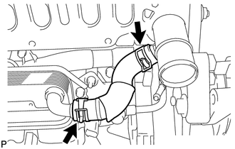
Slide the 2 clamps and remove the water by-pass hose from the oil cooler assembly and water outlet.
-
-
REMOVE OIL COOLER ASSEMBLY
-
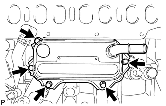
Remove the 5 bolts and oil cooler assembly.
-
Remove the 3 O-rings from the No. 1 oil cooler bracket.
-