МАСЛЯНЫЙ НАСОС ПРОВЕРКА

PROCEDURE
-
INSPECT OIL PUMP
-
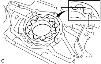
*1 Mark Install the drive rotor and driven rotor to the timing chain cover sub-assembly with the marks of the rotor facing the cylinder block sub-assembly side. Check that the rotors revolve smoothly.
-
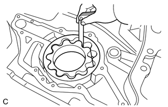
Check the tip clearance.
-
Using a feeler gauge, measure the clearance between the drive rotor and driven rotor tips.
Standard tip clearance 0.180 to 0.300 mm (0.00709 to 0.0118 in.) Maximum tip clearance 0.300 mm (0.0118 in.) If the tip clearance is more than the maximum, replace the timing chain cover sub-assembly.
-
-
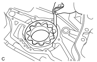
Check the body clearance.
-
Using a feeler gauge, measure the clearance between the oil pump body and driven rotor.
Standard body clearance 0.175 to 0.250 mm (0.00689 to 0.00984 in.) Maximum body clearance 0.250 mm (0.00984 in.) If the body clearance is more than the maximum, replace the timing chain cover sub-assembly.
-
-
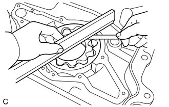
Check the side clearance.
-
Using a feeler gauge and precision straightedge, measure the clearance between the rotors and precision straightedge.
Standard side clearance 0.030 to 0.090 mm (0.00118 to 0.00354 in.) Maximum side clearance 0.090 mm (0.00354 in.) If the side clearance is more than the maximum, replace the timing chain cover sub-assembly.
-
-