ВЫПУСКНОЙ КОЛЛЕКТОР С ТУРБОНАГНЕТАТЕЛЕМ СНЯТИЕ
PROCEDURE
-
PRECAUTION
Note
After turning the ignition switch off, waiting time may be required before disconnecting the cable from the battery terminal. Therefore, make sure to read the disconnecting the cable from the battery terminal notices before proceeding with work.
-
DISCONNECT CABLE FROM NEGATIVE BATTERY TERMINAL
Note
When disconnecting the cable, some systems need to be initialized after the cable is reconnected.
-
DISCONNECT CABLE FROM POSITIVE BATTERY TERMINAL
-
REMOVE EXHAUST MANIFOLD CONVERTER SUB-ASSEMBLY
-
DRAIN ENGINE COOLANT
-
REMOVE BATTERY CLAMP SUB-ASSEMBLY
-
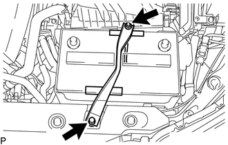
Remove the bolt and loosen the nut.
-
Detach the hook of the battery clamp sub-assembly from the battery carrier assembly, and then remove the battery clamp sub-assembly.
-
-
REMOVE BATTERY INSULATOR
-
REMOVE BATTERY
-
REMOVE BATTERY TRAY
-
REMOVE BATTERY CARRIER ASSEMBLY
-
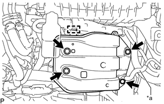
*a Ground Wire Detach the clamp and disconnect the engine wire.
-
Remove the bolt and disconnect the ground wire from the battery carrier assembly.
-
Remove the 3 bolts and battery carrier assembly.
-
-
REMOVE BATTERY BRACKET REINFORCEMENT
-
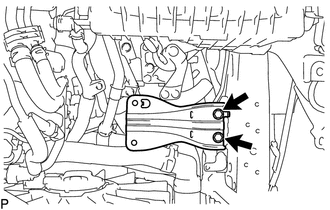
Remove the 2 bolts and battery bracket reinforcement.
-
-
REMOVE AIR CLEANER CAP SUB-ASSEMBLY WITH AIR CLEANER HOSE ASSEMBLY
-
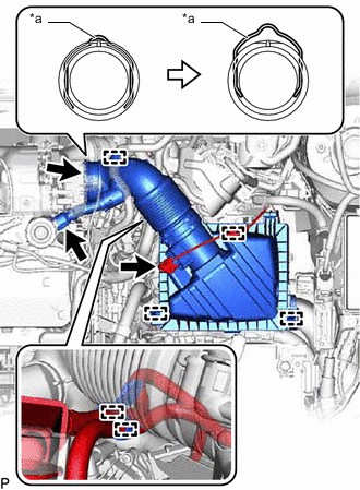
*a Retainer Detach the clamp and disconnect the mass air flow meter sub-assembly connector.
-
Detach the clamp and disconnect the vacuum hose from the air cleaner hose assembly.
-
Detach the clamp and disconnect the No. 1 fuel hose from the air cleaner hose assembly.
-
Detach the clamp and disconnect the No. 2 fuel hose from the air cleaner hose assembly.
-
Disconnect the ventilation hose from the cylinder head cover sub-assembly.
-
Release the retainer and disconnect the air cleaner hose assembly from the turbocharger sub-assembly as shown in the illustration.
-
Detach the 2 clamps and remove the air cleaner cap sub-assembly with air cleaner hose assembly.
-
Remove the air cleaner filter element sub-assembly from the air cleaner case sub-assembly.
-
-
REMOVE AIR CLEANER CASE SUB-ASSEMBLY
-
Remove the 3 bolts and air cleaner case sub-assembly.
-
-
DISCONNECT COMPRESSOR OUTLET ELBOW
-
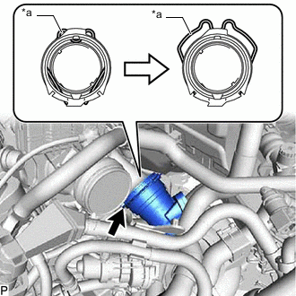
*a Retainer Release the retainer and disconnect the compressor outlet elbow from the turbocharger sub-assembly as shown in the illustration.
-
-
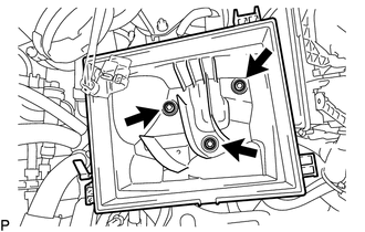
REMOVE TURBO OIL OUTLET PIPE
-
Remove the 3 bolts, turbo oil outlet pipe and gasket.
-
Remove the O-ring from the turbo oil outlet pipe.
-
-
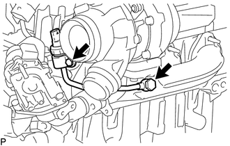
DISCONNECT NO. 1 TURBO OIL PIPE
-
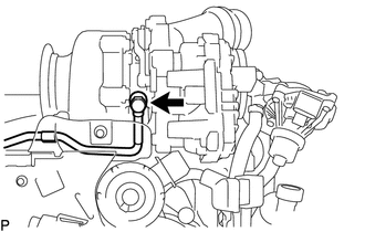
Remove the union bolt and 2 gaskets and disconnect the No. 1 turbo oil pipe.
-
-
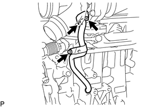
REMOVE NO. 1 EXHAUST MANIFOLD PIPE
-
Disconnect the exhaust manifold pressure sensor connector.
-
Remove the union bolt and 2 gaskets.
-
Remove the bolt and No. 1 exhaust manifold pipe.
-
-
REMOVE TURBOCHARGER SUB-ASSEMBLY
-
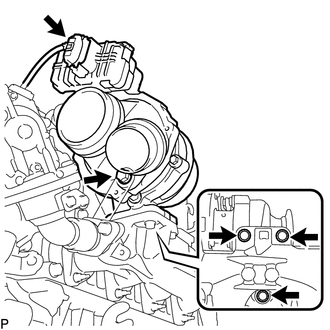
Disconnect the connector from the turbocharger sub-assembly.
-
Remove the 4 bolts, turbocharger sub-assembly and gasket.
-
-
DISCONNECT ENGINE WIRE
-
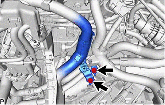
Remove the 2 bolts and disconnect the engine wire from the No. 1 air tube assembly.
-
-
REMOVE NO. 4 WATER BY-PASS HOSE
-
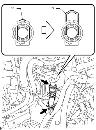
*a Retainer Release the retainer and disconnect the No. 4 water by-pass hose from the EGR cooler assembly as shown in the illustration.
-
Slide the clamp and remove the No. 4 water by-pass hose from the No. 2 radiator pipe.
-
-
DISCONNECT NO. 1 AIR TUBE ASSEMBLY
-
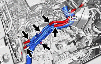
Slide the clamp and disconnect the water by-pass hose assembly from the No. 2 radiator pipe.
-
Slide the clamp and disconnect the radiator hose sub-assembly from the No. 1 radiator pipe.
-
Detach the clamp and disconnect the water hose sub-assembly from the compressor outlet elbow.
-
Slide the clamp and disconnect the water hose sub-assembly from the No. 1 radiator pipe.
-
Slide the clamp and disconnect the outlet heater water hose from the No. 2 radiator pipe.
-
Remove the 2 bolts and disconnect the No. 1 air tube assembly from the manual transaxle assembly.
-
-
DISCONNECT FUEL FEED PIPE SUB-ASSEMBLY
-
REMOVE NO. 1 EXHAUST MANIFOLD HEAT INSULATOR
-
REMOVE EGR COOLER ASSEMBLY WITH EGR VALVE ASSEMBLY
-
REMOVE EXHAUST MANIFOLD
-
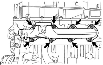
Remove the 8 nuts and exhaust manifold.
-
Remove the 2 gaskets from the cylinder head sub-assembly.
-