СИСТЕМА SFI, Diagnostic DTC:P0351, P0352, P0353, P0354
| DTC Code | DTC Name |
|---|---|
| P0351 | Ignition Coil "A" Primary / Secondary Circuit |
| P0352 | Ignition Coil "B" Primary / Secondary Circuit |
| P0353 | Ignition Coil "C" Primary / Secondary Circuit |
| P0354 | Ignition Coil "D" Primary / Secondary Circuit |
DESCRIPTION
Tech Tips
-
These DTCs indicate malfunctions relating to the primary circuit.
-
If DTC P0351 is output, check the ignition coil assembly (No. 1 cylinder) circuit.
-
If DTC P0352 is output, check the ignition coil assembly (No. 2 cylinder) circuit.
-
If DTC P0353 is output, check the ignition coil assembly (No. 3 cylinder) circuit.
-
If DTC P0354 is output, check the ignition coil assembly (No. 4 cylinder) circuit.
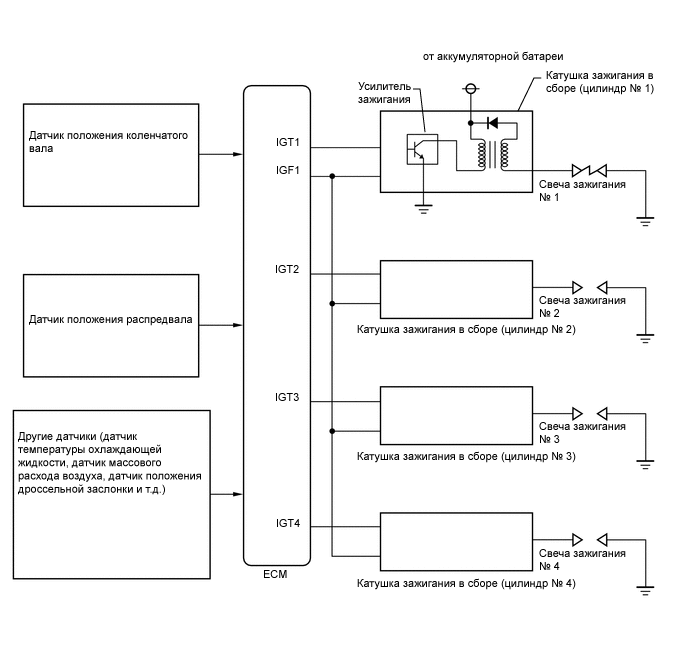
A Direct Ignition System (DIS) is used on this vehicle.
The DIS is a 1-cylinder ignition system in which each cylinder is ignited by one ignition coil assembly and one spark plug is connected to the end of each secondary wiring. A powerful voltage, generated in the secondary wiring, is applied directly to each spark plug. The spark of the spark plugs passes from the center electrode to the ground electrodes.
The ECM determines the ignition timing and transmits the ignition (IGT) signals to each cylinder. Using the IGT signal, the ECM turns the power transistor inside the igniter on and off. The power transistor, in turn, switches the current supplied to the primary coil on and off. When the current to the primary coil is cut off, a powerful voltage is generated in the secondary coil. This voltage is applied to the spark plugs, causing them to spark inside the cylinders. As the ECM cuts the current to the primary coil, the igniter sends back an ignition confirmation (IGF) signal to the ECM for each cylinder ignition.
| DTC No. | Detection Item | DTC Detection Condition | Trouble Area | MIL | Memory |
|---|---|---|---|---|---|
| P0351 | Ignition Coil "A" Primary / Secondary Circuit | No IGF signal to the ECM while the engine is running (1 trip detection logic). |
|
Comes on | DTC stored |
| P0352 | Ignition Coil "B" Primary / Secondary Circuit | No IGF signal to the ECM while the engine is running (1 trip detection logic). |
|
Comes on | DTC stored |
| P0353 | Ignition Coil "C" Primary / Secondary Circuit | No IGF signal to the ECM while the engine is running (1 trip detection logic). |
|
Comes on | DTC stored |
| P0354 | Ignition Coil "D" Primary / Secondary Circuit | No IGF signal to the ECM while the engine is running (1 trip detection logic). |
|
Comes on | DTC stored |
Reference: Inspection using an oscilloscope.
-
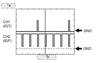
*a 2 V/DIV. *b 20 ms./DIV. -
While idling the engine, check the waveform between terminals IGT (1 to 4) and E1, and IGF1 and E1 of the ECM connector.
ECM Terminal Name CH1: Between IGT (1 to 4) and E1
CH2: Between IGF1 and E1
Tester Range 2 V/DIV., 20 ms./DIV. Condition Idling
MONITOR DESCRIPTION
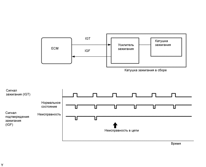
If the ECM does not receive any IGF signals despite transmitting the IGT signal, it interprets this as a fault in the igniter and stores a DTC.
CONFIRMATION DRIVING PATTERN
-
Connect the GTS to the DLC3.
-
Turn the ignition switch to ON and turn the GTS on.
-
Clear the DTCs (even if no DTCs are stored, perform the clear DTC procedure).
-
Turn the ignition switch off and wait for at least 30 seconds.
-
Turn the ignition switch to ON and turn the GTS on.
-
Start the engine.
-
Idle the engine for 10 seconds or more.
-
Enter the following menus: Powertrain / Engine and ECT / Trouble Codes.
-
Read the pending DTCs.
Tech Tips
-
If a pending DTC is output, the system is malfunctioning.
-
If a pending DTC is not output, perform the following procedure.
-
-
Enter the following menus: Powertrain / Engine and ECT / Utility / All Readiness.
-
Input the DTC: P0351, P0352, P0353 or P0354.
-
Check the DTC judgment result.
GTS Display Description NORMAL
-
DTC judgment completed
-
System normal
ABNORMAL
-
DTC judgment completed
-
System abnormal
INCOMPLETE
-
DTC judgment not completed
-
Perform driving pattern after confirming DTC enabling conditions
N/A
-
Unable to perform DTC judgment
-
Number of DTCs which do not fulfill DTC preconditions has reached ECU memory limit
Tech Tips
-
If the judgment result shows NORMAL, the system is normal.
-
If the judgment result shows ABNORMAL, the system has a malfunction.
-
If the judgment result shows INCOMPLETE or N/A, perform the Confirmation Driving Pattern and check the DTC judgment result again.
-
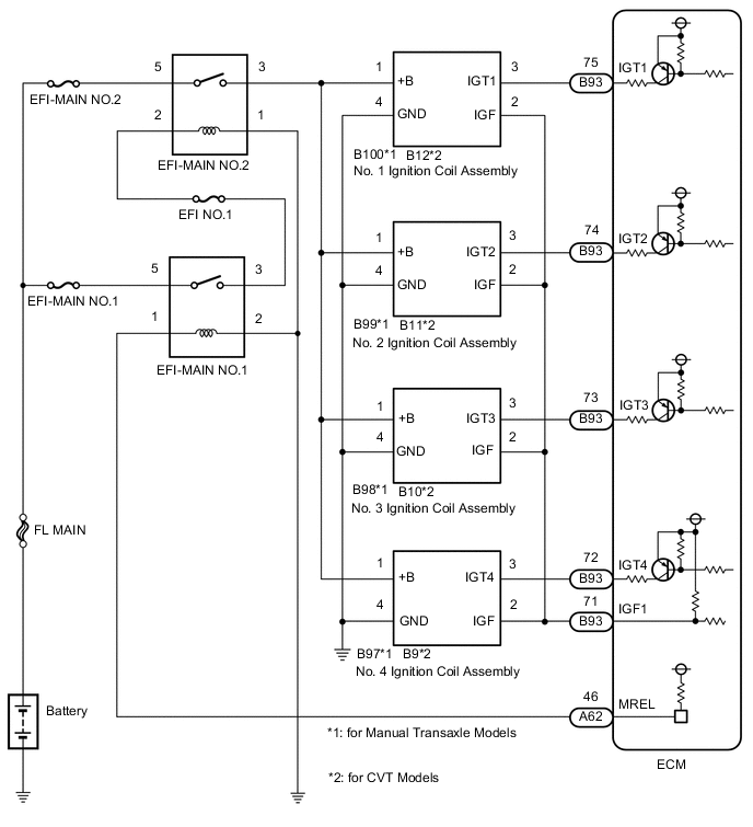
WIRING DIAGRAM
CAUTION / NOTICE / HINT
Note
Inspect the fuses for circuits related to this system before performing the following inspection procedure.
Tech Tips
Read freeze frame data using the GTS. The ECM records vehicle and driving condition information as freeze frame data the moment a DTC is stored. When troubleshooting, freeze frame data can help determine if the vehicle was moving or stationary, if the engine was warmed up or not, if the air fuel ratio was lean or rich, and other data from the time the malfunction occurred.
PROCEDURE
-
CHECK HARNESS AND CONNECTOR (IGNITION COIL ASSEMBLY - BODY GROUND)
-
Disconnect the ignition coil assembly connectors.
-
Measure the resistance according to the value(s) in the table below.
Standard Resistance for Manual Transaxle Models Tester Connection Condition Specified Condition B100-4 (GND) - Body ground Always Below 1 Ω B99-4 (GND) - Body ground Always Below 1 Ω B98-4 (GND) - Body ground Always Below 1 Ω B97-4 (GND) - Body ground Always Below 1 Ω for CVT Models Tester Connection Condition Specified Condition B12-4 (GND) - Body ground Always Below 1 Ω B11-4 (GND) - Body ground Always Below 1 Ω B10-4 (GND) - Body ground Always Below 1 Ω B9-4 (GND) - Body ground Always Below 1 Ω Result Proceed to OK NG
NG 
REPAIR OR REPLACE HARNESS OR CONNECTOR
OK 
-
-
CHECK TERMINAL VOLTAGE (POWER SOURCE OF IGNITION COIL ASSEMBLY)
-
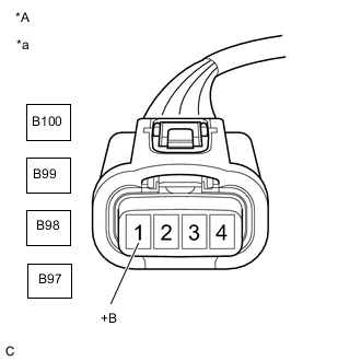
*A for Manual Transaxle Models *a Front view of wire harness connector
(to Ignition Coil Assembly)
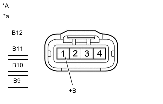
*A for CVT Models *a Front view of wire harness connector
(to Ignition Coil Assembly)
Disconnect the ignition coil assembly connectors.
-
Turn the ignition switch to ON.
-
Measure the voltage according to the value(s) in the table below.
Standard Voltage for Manual Transaxle Models Tester Connection Condition Specified Condition B100-1 (+B) - B100-4 (GND) Ignition switch ON 11 to 14 V B99-1 (+B) - B99-4 (GND) Ignition switch ON 11 to 14 V B98-1 (+B) - B98-4 (GND) Ignition switch ON 11 to 14 V B97-1 (+B) - B97-4 (GND) Ignition switch ON 11 to 14 V for CVT Models Tester Connection Condition Specified Condition B12-1 (+B) - B12-4 (GND) Ignition switch ON 11 to 14 V B11-1 (+B) - B11-4 (GND) Ignition switch ON 11 to 14 V B10-1 (+B) - B10-4 (GND) Ignition switch ON 11 to 14 V B9-1 (+B) - B9-4 (GND) Ignition switch ON 11 to 14 V Result Proceed to OK NG
NG 
CHECK HARNESS AND CONNECTOR (IGNITION COIL ASSEMBLY - EFI-MAIN NO.2 RELAY) Click here
OK
-
-
CHECK HARNESS AND CONNECTOR (IGNITION COIL ASSEMBLY - ECM)
-
Disconnect the ignition coil assembly connectors.
-
Disconnect the ECM connector.
-
Measure the resistance according to the value(s) in the table below.
Standard Resistance for Manual Transaxle Models Tester Connection Condition Specified Condition B100-2 (IGF) - B93-71 (IGF1) Always Below 1 Ω B99-2 (IGF) - B93-71 (IGF1) Always Below 1 Ω B98-2 (IGF) - B93-71 (IGF1) Always Below 1 Ω B97-2 (IGF) - B93-71 (IGF1) Always Below 1 Ω B100-3 (IGT1) - B93-75 (IGT1) Always Below 1 Ω B99-3 (IGT2) - B93-74 (IGT2) Always Below 1 Ω B98-3 (IGT3) - B93-73 (IGT3) Always Below 1 Ω B97-3 (IGT4) - B93-72 (IGT4) Always Below 1 Ω B100-2 (IGF) or B93-71 (IGF1) - Body ground Always 10 kΩ or higher B99-2 (IGF) or B93-71 (IGF1) - Body ground Always 10 kΩ or higher B98-2 (IGF) or B93-71 (IGF1) - Body ground Always 10 kΩ or higher B97-2 (IGF) or B93-71 (IGF1) - Body ground Always 10 kΩ or higher B100-3 (IGT1) or B93-75 (IGT1) - Body ground Always 10 kΩ or higher B99-3 (IGT2) or B93-74 (IGT2) - Body ground Always 10 kΩ or higher B98-3 (IGT3) or B93-73 (IGT3) - Body ground Always 10 kΩ or higher B97-3 (IGT4) or B93-72 (IGT4) - Body ground Always 10 kΩ or higher for CVT Models Tester Connection Condition Specified Condition B12-2 (IGF) - B93-71 (IGF1) Always Below 1 Ω B11-2 (IGF) - B93-71 (IGF1) Always Below 1 Ω B10-2 (IGF) - B93-71 (IGF1) Always Below 1 Ω B9-2 (IGF) - B93-71 (IGF1) Always Below 1 Ω B12-3 (IGT1) - B93-75 (IGT1) Always Below 1 Ω B11-3 (IGT2) - B93-74 (IGT2) Always Below 1 Ω B10-3 (IGT3) - B93-73 (IGT3) Always Below 1 Ω B9-3 (IGT4) - B93-72 (IGT4) Always Below 1 Ω B12-2 (IGF) or B93-71 (IGF1) - Body ground Always 10 kΩ or higher B11-2 (IGF) or B93-71 (IGF1) - Body ground Always 10 kΩ or higher B10-2 (IGF) or B93-71 (IGF1) - Body ground Always 10 kΩ or higher B9-2 (IGF) or B93-71 (IGF1) - Body ground Always 10 kΩ or higher B12-3 (IGT1) or B93-75 (IGT1) - Body ground Always 10 kΩ or higher B11-3 (IGT2) or B93-74 (IGT2) - Body ground Always 10 kΩ or higher B10-3 (IGT3) or B93-73 (IGT3) - Body ground Always 10 kΩ or higher B9-3 (IGT4) or B93-72 (IGT4) - Body ground Always 10 kΩ or higher Result Proceed to OK NG
NG
REPAIR OR REPLACE HARNESS OR CONNECTOR
OK
-
-
CHECK WHETHER DTC OUTPUT RECURS (DTC P0351, P0352, P0353 OR P0354)
-
Connect the GTS to the DLC3.
-
Turn the ignition switch to ON.
-
Turn the GTS on.
-
Clear the DTCs.
Powertrain > Engine and ECT > Clear DTCs -
Shuffle the arrangement of the ignition coil assemblies (among No. 1 to No. 4 cylinders).
Note
Do not change the location of the connectors.
-
Perform a simulation test.
-
Enter the following menus: Powertrain / Engine and ECT / Trouble Codes.
-
Read the DTCs.
Powertrain > Engine and ECT > Trouble CodesResult Result Proceed to Same DTC output A Different ignition coil DTC output B
A
REPLACE ECM Click here
B
REPLACE IGNITION COIL ASSEMBLY Click here
-
-
CHECK HARNESS AND CONNECTOR (IGNITION COIL ASSEMBLY - EFI-MAIN NO.2 RELAY)
-
Disconnect the ignition coil assembly connectors.
-
Remove the EFI-MAIN NO.2 relay from the engine room relay block and junction block assembly.
-
Measure the resistance according to the value(s) in the table below.
Standard Resistance for Manual Transaxle Models Tester Connection Condition Specified Condition B100-1 (+B) - 3 (EFI-MAIN NO.2 relay) Always Below 1 Ω B99-1 (+B) - 3 (EFI-MAIN NO.2 relay) Always Below 1 Ω B98-1 (+B) - 3 (EFI-MAIN NO.2 relay) Always Below 1 Ω B97-1 (+B) - 3 (EFI-MAIN NO.2 relay) Always Below 1 Ω B100-1 (+B) or 3 (EFI-MAIN NO.2 relay) - Body ground Always 10 kΩ or higher B99-1 (+B) or 3 (EFI-MAIN NO.2 relay) - Body ground Always 10 kΩ or higher B98-1 (+B) or 3 (EFI-MAIN NO.2 relay) - Body ground Always 10 kΩ or higher B97-1 (+B) or 3 (EFI-MAIN NO.2 relay) - Body ground Always 10 kΩ or higher for CVT Models Tester Connection Condition Specified Condition B12-1 (+B) - 3 (EFI-MAIN NO.2 relay) Always Below 1 Ω B11-1 (+B) - 3 (EFI-MAIN NO.2 relay) Always Below 1 Ω B10-1 (+B) - 3 (EFI-MAIN NO.2 relay) Always Below 1 Ω B9-1 (+B) - 3 (EFI-MAIN NO.2 relay) Always Below 1 Ω B12-1 (+B) or 3 (EFI-MAIN NO.2 relay) - Body ground Always 10 kΩ or higher B11-1 (+B) or 3 (EFI-MAIN NO.2 relay) - Body ground Always 10 kΩ or higher B10-1 (+B) or 3 (EFI-MAIN NO.2 relay) - Body ground Always 10 kΩ or higher B9-1 (+B) or 3 (EFI-MAIN NO.2 relay) - Body ground Always 10 kΩ or higher Result Proceed to OK NG
NG
REPAIR OR REPLACE HARNESS OR CONNECTOR
OK
-
-
CHECK TERMINAL VOLTAGE (POWER SOURCE OF EFI-MAIN NO.2 RELAY)
-
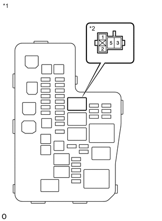
*1 Engine Room Relay Block and Junction Block Assembly *2 EFI-MAIN NO.2 Relay Remove the EFI-MAIN NO.2 relay from the engine room relay block and junction block assembly.
-
Measure the voltage according to the value(s) in the table below.
Standard Voltage Tester Connection Condition Specified Condition 5 (EFI-MAIN NO.2 relay) - Body ground Always 11 to 14 V Result Proceed to OK NG
NG
REPAIR OR REPLACE HARNESS OR CONNECTOR (EFI-MAIN NO.2 RELAY - BATTERY)
OK
-
-
INSPECT EFI-MAIN NO.2 RELAY
-
Inspect the EFI-MAIN NO.2 relay.
Result Proceed to OK NG
NG
REPLACE EFI-MAIN NO.2 RELAY
OK
-
-
CHECK HARNESS OR CONNECTOR (EFI-MAIN NO.2 RELAY - BODY GROUND)
-
Remove the EFI-MAIN NO.2 relay from the engine room relay block and junction block assembly.
-
Measure the resistance according to the value(s) in the table below.
Standard Resistance Tester Connection Condition Specified Condition 1 (EFI-MAIN NO.2 relay) - Body ground Always Below 1 Ω Result Proceed to OK NG
OK
REPAIR OR REPLACE HARNESS AND CONNECTOR (EFI-MAIN NO.2 RELAY - EFI-MAIN NO.1 RELAY)
NG
REPAIR OR REPLACE HARNESS OR CONNECTOR (EFI-MAIN NO.2 RELAY - BODY GROUND)
-