СИСТЕМА ECD VC Output Circuit
DESCRIPTION
The ECM constantly generates 5 V of power from the battery voltage supplied to the +B (BATT) terminal to operate the microprocessor. The ECM also provides this power to the sensors through the VC output circuit.
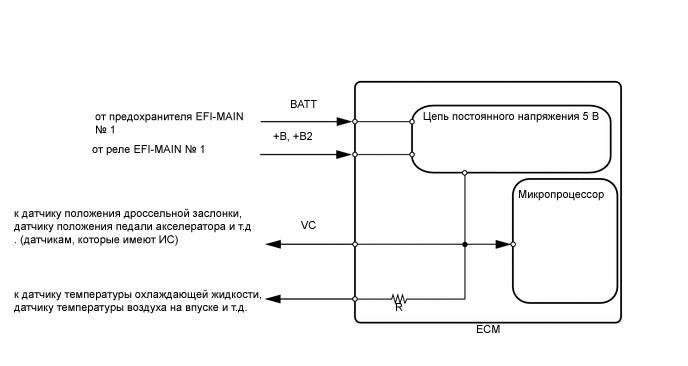
When the VC circuit is short-circuited, the microprocessor in the ECM and sensors that are supplied with power through the VC circuit are deactivated because the power is not supplied from the VC circuit. Under this condition, the system does not start up and the MIL does not illuminate even if the system malfunctions.
Tech Tips
Under normal conditions, the MIL is illuminated when the ignition switch is turned ON. The MIL goes off when the engine is started.
WIRING DIAGRAM
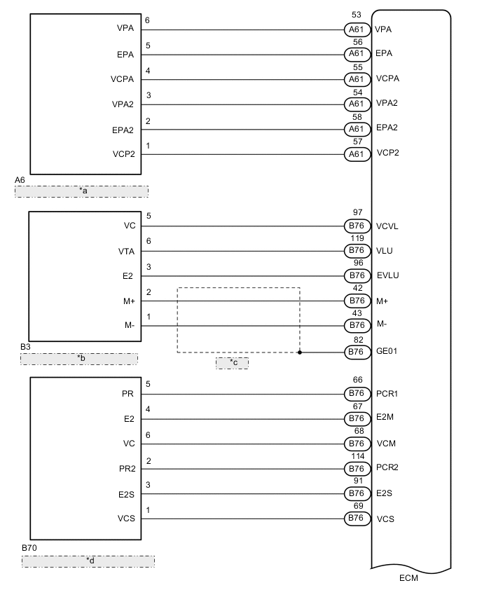
| *a | Accelerator Pedal Sensor Assembly |
| *b | Diesel Throttle Body Assembly |
| *c | Shielded |
| *d | Fuel Pressure Sensor (Built into Common Rail Assembly) |
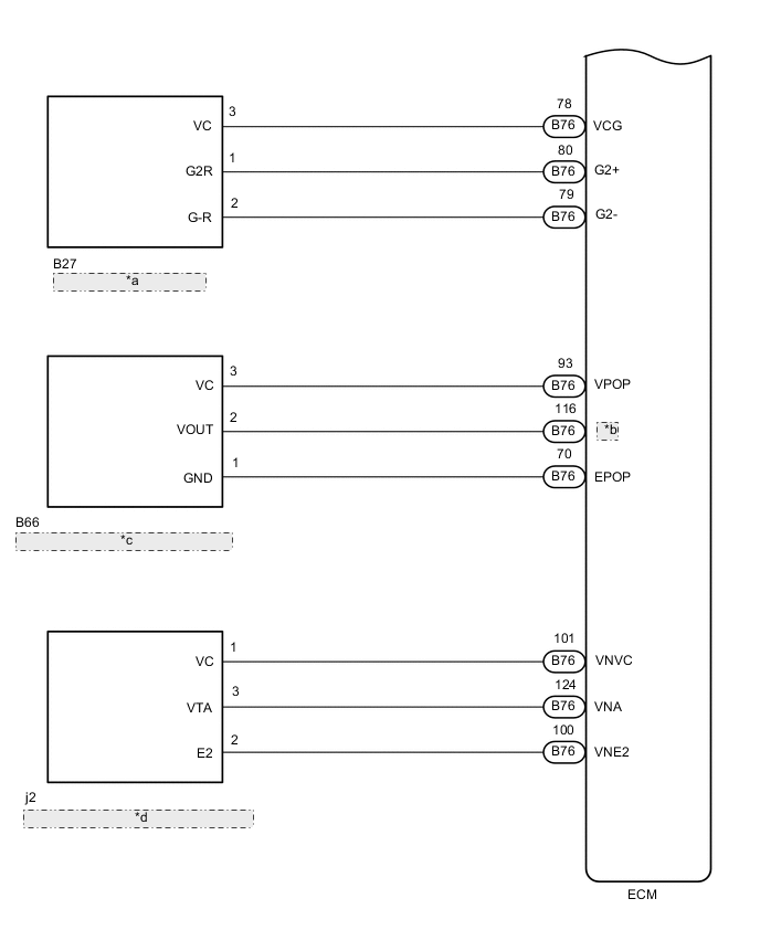
| *a | Camshaft Position Sensor |
| *b | POP |
| *c | Oil Pressure Sender Gauge Assembly |
| *d | Nozzle Vane Position Sensor (Built into Turbocharger Sub-assembly) |
CAUTION / NOTICE / HINT
Note
After replacing the ECM, the new ECM needs registration (Click here) and initialization Click here.
PROCEDURE
-
CHECK MIL
-
Check that the Malfunction Indicator Lamp (MIL) illuminates when turning the ignition switch to ON.
Result Result Proceed to MIL does not illuminate A MIL illuminates B
B 
PROCEED TO NEXT SUSPECTED AREA SHOWN IN PROBLEM SYMPTOMS TABLE Click here
A 
-
-
CHECK COMMUNICATION BETWEEN GTS AND ECM
-
Connect the GTS to the DLC3.
-
Turn the ignition switch to ON and GTS on.
-
Check the communication between the GTS and ECM.
Result Result Proceed to Communication is not possible A Communication is possible B
B
GO TO MIL CIRCUIT Click here
A
-
-
CHECK MIL (ACCELERATOR PEDAL SENSOR ASSEMBLY)
-
Disconnect the accelerator pedal sensor assembly connector.
-
Turn the ignition switch to ON.
-
Check the MIL.
Result Result Proceed to MIL does not illuminate A MIL illuminates B
B
REPLACE ACCELERATOR PEDAL SENSOR ASSEMBLY Click here
A
-
-
CHECK MIL (DIESEL THROTTLE BODY ASSEMBLY)
-
Disconnect the diesel throttle body assembly connector.
-
Turn the ignition switch to ON.
-
Check the MIL.
Result Result Proceed to MIL does not illuminate A MIL illuminates B
B
REPLACE DIESEL THROTTLE BODY ASSEMBLY Click here
A
-
-
CHECK MIL (FUEL PRESSURE SENSOR)
-
Disconnect the fuel pressure sensor connector.
-
Turn the ignition switch to ON.
-
Check the MIL.
Result Result Proceed to MIL does not illuminate A MIL illuminates B
B
REPLACE COMMON RAIL ASSEMBLY Click here
A
-
-
CHECK MIL (ELECTRIC EGR CONTROL VALVE ASSEMBLY)
-
Disconnect the electric EGR control valve assembly connector.
-
Turn the ignition switch to ON.
-
Check the MIL.
Result Result Proceed to MIL does not illuminate A MIL illuminates B
B
REPLACE ELECTRIC EGR CONTROL VALVE ASSEMBLY Click here
A
-
-
CHECK MIL (DIFFERENTIAL PRESSURE SENSOR ASSEMBLY)
-
Disconnect the differential pressure sensor assembly connector.
-
Turn the ignition switch to ON.
-
Check the MIL.
Result Result Proceed to MIL does not illuminate A MIL illuminates B
B
REPLACE DIFFERENTIAL PRESSURE SENSOR ASSEMBLY Click here
A
-
-
CHECK MIL (MANIFOLD ABSOLUTE PRESSURE SENSOR)
-
Disconnect the manifold absolute pressure sensor connector.
-
Turn the ignition switch to ON.
-
Check the MIL.
Result Result Proceed to MIL does not illuminate A MIL illuminates B
B
REPLACE MANIFOLD ABSOLUTE PRESSURE SENSOR Click here
A
-
-
CHECK MIL (CAMSHAFT POSITION SENSOR)
-
Disconnect the camshaft position sensor connector.
-
Turn the ignition switch to ON.
-
Check the MIL.
Result Result Proceed to MIL does not illuminate A MIL illuminates B
B
REPLACE CAMSHAFT POSITION SENSOR Click here
A
-
-
CHECK MIL (OIL PRESSURE SENDER GAUGE ASSEMBLY)
-
Disconnect the oil pressure sender gauge assembly connector.
-
Turn the ignition switch to ON.
-
Check the MIL.
Result Result Proceed to MIL does not illuminate A MIL illuminates B
B
REPLACE OIL PRESSURE SENDER GAGE ASSEMBLY Click here
A
-
-
CHECK MIL (NOZZLE VANE POSITION SENSOR)
-
Disconnect the nozzle vane position sensor connector.
-
Turn the ignition switch to ON.
-
Check the MIL.
Result Result Proceed to MIL does not illuminate A MIL illuminates B
B
REPLACE TURBOCHARGER SUB-ASSEMBLY Click here
A
-
-
CHECK HARNESS AND CONNECTOR
-
Disconnect the accelerator pedal sensor assembly connector.
-
Disconnect the diesel throttle body assembly connector.
-
Disconnect the fuel pressure sensor connector.
-
Disconnect the electric EGR control valve assembly connector.
-
Disconnect the differential pressure sensor assembly connector.
-
Disconnect the manifold absolute pressure sensor connector.
-
Disconnect the camshaft position sensor connector.
-
Disconnect the oil pressure sender gauge assembly connector.
-
Disconnect the nozzle vane position sensor connector.
-
Disconnect the ECM connectors.
-
Measure the resistance according to the value(s) in the table below.
Standard Resistance Tester Connection Condition Specified Condition A61-55 (VCPA) - Body ground Always 10 kΩ or higher A61-57 (VCP2) - Body ground Always 10 kΩ or higher B76-97 (VCVL) - Body ground Always 10 kΩ or higher B76-68 (VCM) - Body ground Always 10 kΩ or higher B76-69 (VCS) - Body ground Always 10 kΩ or higher B76-94 (VCEG) - Body ground Always 10 kΩ or higher B76-75 (VCPM) - Body ground Always 10 kΩ or higher B76-78 (VCG) - Body ground Always 10 kΩ or higher B76-93 (VPOP) - Body ground Always 10 kΩ or higher B76-101 (VNVC) - Body ground Always 10 kΩ or higher Result Proceed to OK NG
OK
REPLACE ECM Click here
NG
REPAIR OR REPLACE HARNESS OR CONNECTOR
-