ВПУСКНОЙ КОЛЛЕКТОР УСТАНОВКА

PROCEDURE
-
INSTALL STUD BOLT
Tech Tips
If a stud bolt is deformed or the threads are damaged, replace it.
-
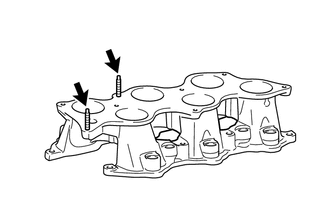
Using an E6 "TORX" socket wrench, install the 2 stud bolts to the intake manifold.
- Torque:
- 4.0 N*m { 41 kgf*cm, 35 in.*lbf }
-
-
INSTALL INTAKE MANIFOLD
-
Set 2 new gaskets on the cylinder head sub-assembly.
Note
-
Align the port holes of the gaskets and cylinder head sub-assembly.
-
Make sure that the gaskets are installed in the correct direction.
-
-
Set the intake manifold on the cylinder head sub-assembly.
-
Temporarily install the intake manifold with the 4 bolts and 4 nuts.
-
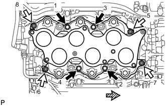

Bolt 
Nut 
Front Tighten the 4 bolts and 4 nuts in the order shown in the illustration.
- Torque:
- 21 N*m { 214 kgf*cm, 15 ft.*lbf }
-
-
INSTALL FUEL DELIVERY PIPE SUB-ASSEMBLY
-
INSTALL INTAKE AIR SURGE TANK ASSEMBLY
Note
Do not apply oil to the bolts listed below.
Oil Application Prohibited Bolt Bolt for Intake Air Surge Tank Assembly and Intake Manifold Bolt for No. 1 Surge Tank Stay and Intake Air Surge Tank Assembly
-
Install 3 new gaskets to the intake air surge tank assembly.
-
Temporarily install the intake air surge tank assembly with the 6 bolts and 2 nuts.
-
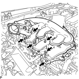
Bolt Nut Using a 5 mm hexagon socket wrench, tighten the 6 bolts and 2 nuts in the order shown in the illustration.
- Torque:
- Bolt
- 18 N*m { 184 kgf*cm, 13 ft.*lbf }
- Nut
- 16 N*m { 163 kgf*cm, 12 ft.*lbf }
-
Connect the No. 2 surge tank stay to the intake air surge tank assembly with the bolt.
- Torque:
- 21 N*m { 214 kgf*cm, 15 ft.*lbf }
-
Connect the No. 3 water by-pass pipe to the intake air surge tank assembly with the bolt.
- Torque:
- 10 N*m { 102 kgf*cm, 7 ft.*lbf }
-
Connect the 5 wire harness clamps to the intake air surge tank assembly.
-
Connect the No. 2 water by-pass hose to the intake air surge tank assembly clamp.
-
Connect the union to check valve hose to the intake air surge tank assembly and slide the clip to secure it.
-
Connect the ventilation hose assembly to the PCV valve (ventilation valve sub-assembly) and slide the clip to secure it.
-
Connect the purge valve (purge VSV) to the intake air surge tank assembly with the bolt.
- Torque:
- 18 N*m { 184 kgf*cm, 13 ft.*lbf }
-
Connect the No. 1 fuel vapor feed hose to the purge valve (purge VSV).
-
Connect the purge valve (purge VSV) connector.
-
-
INSTALL COWL TOP VENTILATOR LOUVER SUB-ASSEMBLY
-
INSTALL THROTTLE BODY WITH MOTOR ASSEMBLY
-
CONNECT CABLE TO NEGATIVE BATTERY TERMINAL
Note
When disconnecting the cable, some systems need to be initialized after the cable is reconnected.
-
INSPECT FOR FUEL LEAK