ТОПЛИВНАЯ ФОРСУНКА (для непосредственного впрыска) СНЯТИЕ

PROCEDURE
-
REMOVE FUEL PUMP ASSEMBLY
-
REMOVE NO. 3 FUEL PIPE SUB-ASSEMBLY
-
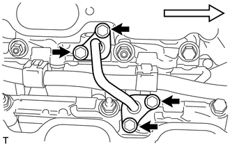

Front Remove the 4 bolts and No. 3 fuel pipe sub-assembly from the fuel delivery pipe sub-assembly.
Note
Pull and remove the No. 3 fuel pipe sub-assembly in a straight line to avoid damage to the seal surface of the delivery pipe O-rings.
-
Remove the 2 O-rings, No. 1 back-up ring, No. 2 back-up ring, No. 3 back-up ring and 2 E-rings from the No. 3 fuel pipe sub-assembly.
-
-
REMOVE NO. 2 FUEL DELIVERY PIPE SUB-ASSEMBLY
-
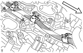
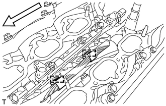
Front Side Disconnect the 3 wire harness clamps.
-

Nut Bolt 
Front Side Remove the 2 bolts and 2 nuts.
-
Front Side With the connectors still connected, disconnect the No. 2 fuel delivery pipe sub-assembly.
Note
-
Make sure that the fuel delivery pipe sub-assembly and No. 2 fuel delivery pipe sub-assembly are disconnected from the No. 2 fuel delivery pipe sub-assembly.
-
Be extremely careful not to touch or strike the tips of the fuel injector assembly.
-
Pull and remove the fuel pipe in a straight line without tilting it.
-
-
Disconnect the 3 fuel injector assembly connectors.
-
Remove the 3 injector vibration insulators from the cylinder head sub-assembly.
-
-
REMOVE FUEL DELIVERY PIPE SUB-ASSEMBLY
-
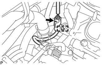
Disconnect the fuel pressure sensor connector and wire harness clamp.
-
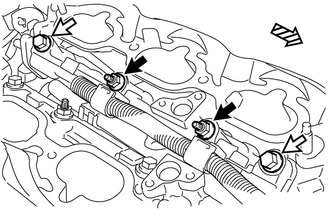
Front Side Disengage the 2 wire harness clamps.
-
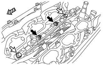
Nut Bolt Front Side Remove the 2 bolts and 2 nuts.
-
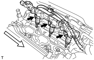
Front Side With the connectors still connected, disconnect the fuel delivery pipe sub-assembly.
Note
-
Be extremely careful not to touch or strike the tips of the fuel injector assembly.
-
Pull and remove the fuel delivery pipe sub-assembly in a straight line without tilting it.
-
-
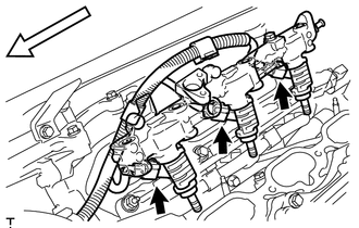
Disconnect the 3 fuel injector assembly connectors.
-
Remove the 3 injector vibration insulators from the cylinder head sub-assembly.
-
-
REMOVE FUEL INJECTOR ASSEMBLY
-
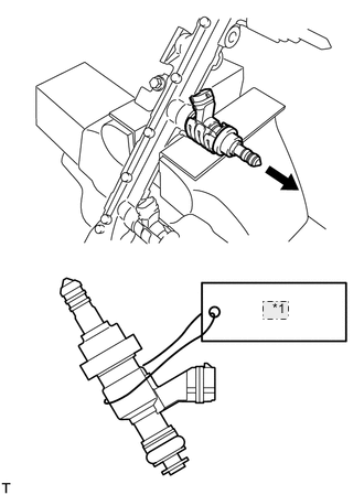
*1 NO.1 Secure the fuel delivery pipe sub-assembly and No. 2 fuel delivery pipe sub-assembly in a vise between aluminum plates and pull out the 6 fuel injector assemblies.
Note
-
Pull and remove each fuel injector assembly in a straight line to avoid damage to the seal surface of the fuel delivery pipe sub-assembly and No. 2 fuel delivery pipe sub-assembly O-ring.
-
For reinstallation, attach a tag or label with the corresponding cylinder number to each fuel injector assembly.
-
-
Remove the nozzle holder clamp from each fuel injector assembly.
-
Remove the O-ring, No. 1 back-up ring, No. 2 back-up ring, No. 3 back-up ring, and E-ring from each fuel injector assembly.
-
-
REMOVE FUEL INJECTOR SEAL
-
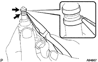
Using the tip of needle nose pliers, pinch and pull either of the 2 fuel injector seals at several points to stretch it. Repeat this for the other fuel injector seal.
Note
-
Excessively pinching the fuel injector seal may damage the groove of the fuel injector assembly.
-
If a fuel injector assembly is dropped or the tip of a fuel injector assembly is struck, replace it with a new one.
-
-
Remove the 2 fuel injector seals from the fuel injector assembly.
-