БЛОК ДВИГАТЕЛЯ ПРОВЕРКА

PROCEDURE
-
INSPECT NO. 1 VALVE ROCKER ARM SUB-ASSEMBLY
-
Turn the roller by hand to check that it turns smoothly.
If the roller does not turn smoothly, replace the No. 1 valve rocker arm sub-assembly.
-
-
INSPECT VALVE LASH ADJUSTER ASSEMBLY
Note
-
Keep the valve lash adjuster assembly free of dirt and foreign objects.
-
Only use clean engine oil.
-
Place the valve lash adjuster assembly into a container filled with engine oil.
-
Insert the tip of SST into the valve lash adjuster assembly plunger and use the tip to press down on the check ball inside the plunger.
- SST
- 09276-75010
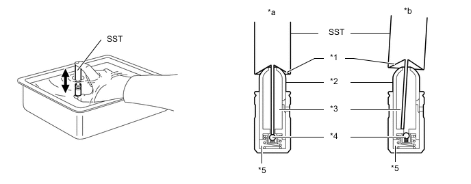
*1 Tapered Path *2 Plunger *3 Low Pressure Chamber *4 Check Ball *5 High Pressure Chamber - - *a CORRECT *b INCORRECT -
Squeeze SST and the valve lash adjuster assembly together to move the plunger up and down 5 to 6 times.
-
Check the movement of the plunger and bleed air.
OK Plunger moves up and down. Note
When bleeding air from the high-pressure chamber, make sure that the tip of SST is actually pressing the check ball as shown in the illustration.
If the check ball is not pressed, air will not bleed.
-
After bleeding air, remove SST. Then try to quickly and firmly press the plunger with your fingers.
OK Plunger is very difficult to move. If the plunger can still be compressed after bleeding air 3 times, replace the valve lash adjuster assembly with a new one.
-
-
INSPECT CAMSHAFT
-
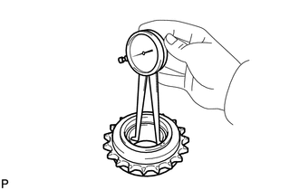
Inspect the camshaft runout.
-
Place the camshaft on V-blocks.
-
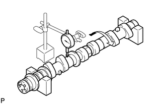
Using a dial indicator, measure the circle runout at the center journal.
Maximum circle runout 0.04 mm (0.00157 in.) If the runout is more than the maximum, replace the camshaft.
-
-
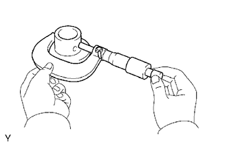
Using a micrometer, measure the cam lobe height.
Standard Cam Lobe Height Item Specified Condition Intake 44.318 to 44.418 mm (1.7448 to 1.7487 in.) Exhaust 44.341 to 44.441 mm (1.7457 to 1.7496 in.) Exhaust (for Fuel Pump) 56.450 to 56.550 mm (2.2224 to 2.2264 in.) Minimum Cam Lobe Height Item Specified Condition Intake 44.168 mm (1.7389 in.) Exhaust 44.191 mm (1.7398 in.) Exhaust (for Fuel Pump) 56.300 mm (2.2165 in.) -
Using a micrometer, measure the journal diameter.
Standard Journal Diameter Item Specification No. 1 journal 35.946 to 35.960 mm (1.4152 to 1.4157 in.) Other journals 25.959 to 25.975 mm (1.0220 to 1.0226 in.) If the journal diameter is not as specified, check the oil clearance.
-
-
INSPECT CAMSHAFT TIMING GEAR ASSEMBLY
-
Install the camshaft timing gear assembly.
-
Inspect the camshaft timing gear assembly.
-
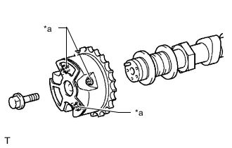
*a Do Not Remove Remove the flange bolt and camshaft timing gear assembly.
Note
-
Do not remove the other 3 bolts.
-
If planning to reuse the camshaft timing gear assembly, be sure to release the straight pin lock before installing the camshaft timing gear assembly.
-
-
-
INSPECT CAMSHAFT TIMING EXHAUST GEAR ASSEMBLY
-
Install the camshaft timing exhaust gear assembly.
-
Inspect the camshaft timing exhaust gear assembly.
-
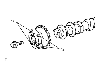
*a Do Not Remove Remove the flange bolt and camshaft timing exhaust gear assembly.
Note
-
Be sure not to remove the other 4 bolts.
-
If planning to reuse the camshaft timing exhaust gear assembly, be sure to release the straight pin lock before installing the camshaft timing exhaust gear assembly.
-
-
-
INSPECT CYLINDER HEAD SET BOLT
-
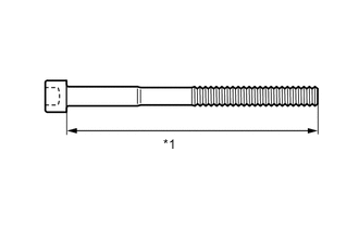
*1 Measurement Length Using a vernier caliper, measure the length of the cylinder head set bolt from the seat to the end.
Standard length 141.3 to 142.7 mm (5.56 to 5.62 in.) Maximum length 143.7 mm (5.66 in.) If the length is more than the maximum, replace the cylinder head set bolt.
-
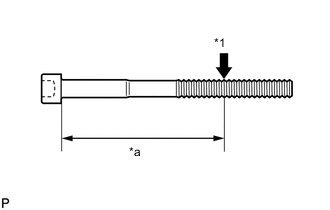
*1 Measurement Point *a Approximately 100 mm (3.94 in.) Using a vernier caliper, measure the diameter of the elongated thread at the measurement point.
Standard diameter 10.80 to 11.00 mm (0.425 to 0.433 in.) Minimum diameter 10.70 mm (0.421 in.) Note
-
If the diameter is less than the minimum, replace the cylinder head set bolt. Failure to do so may lead to engine damage.
-
If there is any thread deformation, replace the cylinder head set bolt with a new one.
-
-
-
INSPECT CHAIN SUB-ASSEMBLY
-
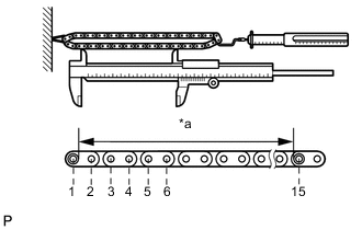
*a Measurement Area Using a spring scale, pull the chain sub-assembly with a force of 147 N (15 kgf, 33 lbf) and measure the length of the chain sub-assembly using a vernier caliper.
Maximum chain elongation 136.9 mm (5.39 in.) Tech Tips
Perform the measurement at 3 random places. If a measurement is more than the maximum, replace the chain sub-assembly.
-
-
INSPECT NO.2 CHAIN SUB-ASSEMBLY
-
*a Measurement Area Using a spring scale, pull the No. 2 chain sub-assembly with a force of 147 N (15 kgf, 33 lbf) and measure the length of the No. 2 chain sub-assembly using a vernier caliper.
Maximum chain elongation 137.6 mm (5.42 in.) Tech Tips
Perform the measurement at 3 random places. If a measurement is more than the maximum, replace the No. 2 chain sub-assembly.
-
-
INSPECT CRANKSHAFT TIMING GEAR OR SPROCKET
-
Place the chain sub-assembly around the crankshaft timing gear or sprocket.
-
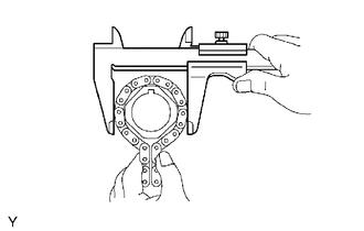
Using a vernier caliper, measure the sprocket diameter with the chain sub-assembly.
Minimum sprocket diameter (with chain sub-assembly) 61.4 mm (2.42 in.) Tech Tips
The vernier caliper must contact the chain rollers for the measurement.
If the diameter is less than the minimum, replace the chain sub-assembly and crankshaft timing gear or sprocket.
-
-
INSPECT IDLE SPROCKET ASSEMBLY
-
Place the chain sub-assembly around the idle sprocket assembly.
-
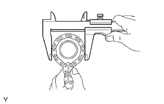
Using a vernier caliper, measure the sprocket diameter with the chain sub-assembly.
Minimum sprocket diameter (with chain sub-assembly) 61.4 mm (2.42 in.) Tech Tips
The vernier caliper must contact the chain rollers for the measurement.
If the diameter is less than the minimum, replace the chain sub-assembly and idle sprocket assembly.
-
-
INSPECT IDLE GEAR SHAFT OIL CLEARANCE
-
Using a micrometer, measure the No. 1 idle gear shaft diameter.
Standard diameter 22.987 to 23.000 mm (0.905 to 0.906 in.) -
Using a caliper gauge, measure the inside diameter of the idle sprocket assembly.
Standard diameter 23.020 to 23.030 mm (0.906 to 0.907 in.) -
Subtract the No. 1 idle gear shaft diameter measurement from the idle sprocket assembly inside diameter measurement.
Standard oil clearance 0.020 to 0.043 mm (0.00079 to 0.00169 in.) Maximum oil clearance 0.093 mm (0.00366 in.) If the oil clearance is more than the maximum, replace the No. 1 idle gear shaft and idle sprocket assembly.
-
-
INSPECT NO. 1 CHAIN TENSIONER ASSEMBLY
-
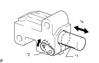
*1 Plunger *2 Stopper Plate *a Moves Smoothly Move the stopper plate upward to release the lock. Push the plunger and check that it moves smoothly.
If necessary, replace the No. 1 chain tensioner assembly.
-
-
INSPECT NO. 2 CHAIN TENSIONER ASSEMBLY
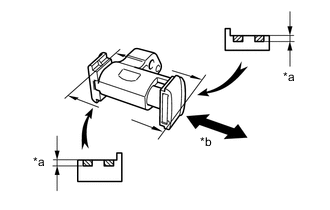
*a Depth *b Moves Smoothly
-
Check that the plunger moves smoothly.
-
Measure the depth of wear of the No. 2 chain tensioner assembly.
Maximum depth 0.9 mm (0.0354 in.) If the depth is more than the maximum, replace the No. 2 chain tensioner assembly.
-
-
INSPECT NO. 3 CHAIN TENSIONER ASSEMBLY
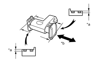
*a Depth *b Moves Smoothly
-
Check that the plunger moves smoothly.
-
Measure the depth of wear of the No. 3 chain tensioner assembly.
Maximum depth 0.9 mm (0.0354 in.) If the depth is more than the maximum, replace the No. 3 chain tensioner assembly.
-
-
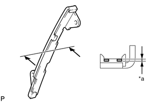
INSPECT CHAIN TENSIONER SLIPPER
-
*a Depth Measure the depth of wear of the chain tensioner slipper.
Maximum depth 1.0 mm (0.0394 in.) If the depth is more than the maximum, replace the chain tensioner slipper.
-
-
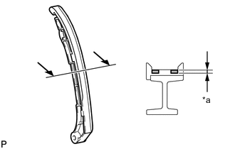
INSPECT NO. 1 CHAIN VIBRATION DAMPER
-
*a Depth Measure the depth of wear of the No. 1 chain vibration damper.
Maximum depth 1.0 mm (0.0394 in.) If the depth is more than the maximum, replace the No. 1 chain vibration damper.
-
-
INSPECT NO. 2 CHAIN VIBRATION DAMPER
-
*a Depth Measure the depth of wear of the No. 2 chain vibration damper.
Maximum depth 1.0 mm (0.0394 in.) If the depth is more than the maximum, replace the No. 2 chain vibration damper.
-
-
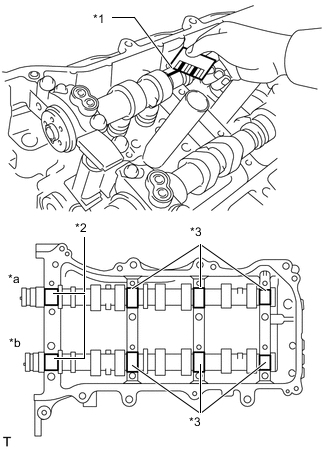
INSPECT CAMSHAFT OIL CLEARANCE
-
for Bank 1:
-
Clean the camshaft bearing caps, camshaft housing sub-assembly RH and camshaft journals.
-
Place the camshafts on the camshaft housing sub-assembly RH.
-
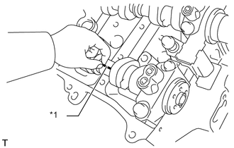
*1 Plastigage Lay a strip of Plastigage across each camshaft journal.
-
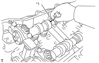
Install the camshaft bearing caps.
Note
Do not turn the camshafts.
-
Remove the camshaft bearing caps.
-
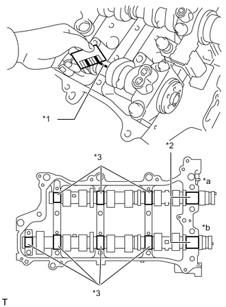
*1 Plastigage *2 No. 1 Journal *3 Other Journals *a Intake Side *b Exhaust Side Measure the Plastigage at its widest point.
Standard Oil Clearance Item Specified Condition Exhaust side No. 1 journal 0.031 to 0.078 mm (0.00122 to 0.00307 in.) Other journals 0.025 to 0.062 mm (0.00098 to 0.00244 in.) Maximum Oil Clearance Item Specified Condition Exhaust side No. 1 journal 0.10 mm (0.00394 in.) Other journals 0.09 mm (0.00354 in.) If the oil clearance is more than the maximum, replace the camshaft.
If the oil clearance is still more than the maximum after replacing the camshaft, replace the camshaft housing sub-assembly RH.
-
-
for Bank 2:
-
Clean the camshaft bearing caps, camshaft housing sub-assembly LH and camshaft journals.
-
Place the camshafts on the camshaft housing sub-assembly LH.
-
*1 Plastigage Lay a strip of Plastigage across each camshaft journal.
-
Install the camshaft bearing caps.
Note
Do not turn the camshafts.
-
Remove the camshaft bearing caps.
-
*1 Plastigage *2 No. 1 Journal *3 Other Journals *a Intake Side *b Exhaust Side Measure the Plastigage at its widest point.
Standard Oil Clearance Item Specified Condition Exhaust side No. 1 journal 0.031 to 0.078 mm (0.00122 to 0.00307 in.) Other journals 0.025 to 0.062 mm (0.00098 to 0.00244 in.) Maximum Oil Clearance Item Specified Condition Exhaust side No. 1 journal 0.10 mm (0.00394 in.) Other journals 0.09 mm (0.00354 in.) If the oil clearance is more than the maximum, replace the camshaft.
If the oil clearance is still more than the maximum after replacing the camshaft, replace the camshaft housing sub-assembly LH.
-
-
-
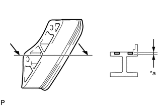
INSPECT EXHAUST MANIFOLD SUB-ASSEMBLY
-
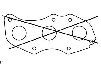
Using a precision straightedge and feeler gauge, measure the warpage of the surface which contacts the cylinder head sub-assembly.
Maximum warpage 0.70 mm (0.02756 in.) If the warpage is more than the maximum, replace the exhaust manifold sub-assembly.
-
-
INSPECT INTAKE MANIFOLD
-
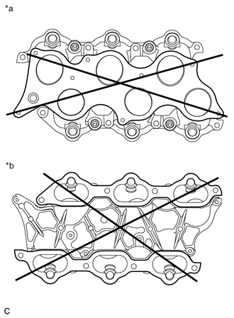
*a Intake Air Surge Tank Side *b Cylinder Head Side Using a precision straightedge and feeler gauge, measure the warpage of the surfaces which contact the cylinder head and intake air surge tank.
Maximum warpage 0.10 mm (0.00394 in.) If the warpage is more than the maximum, replace the intake manifold.
-