ДАТЧИК ПОЛОЖЕНИЯ РАСПРЕДВАЛА СНЯТИЕ

PROCEDURE
-
REMOVE V-BANK COVER SUB-ASSEMBLY
-
REMOVE VVT SENSOR (for Intake Side of Bank 1)
-
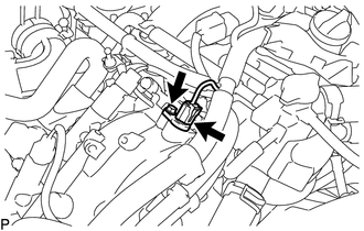
Disconnect the VVT sensor connector.
-
Remove the bolt and VVT sensor from the cylinder head cover sub-assembly.
-
-
REMOVE VVT SENSOR (for Exhaust Side of Bank 1)
-
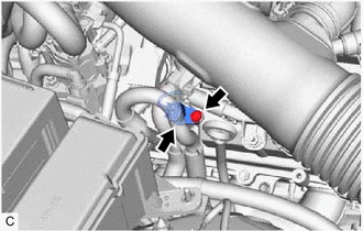
Disconnect the VVT sensor connector.
-
Remove the bolt and VVT sensor from the cylinder head cover sub-assembly.
-
-
REMOVE VVT SENSOR (for Intake Side of Bank 2)
-
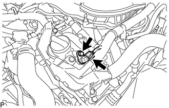
Disconnect the VVT sensor connector.
-
Remove the bolt and VVT sensor from the cylinder head cover sub-assembly LH.
-
-
REMOVE VVT SENSOR (for Exhaust Side of Bank 2)
-
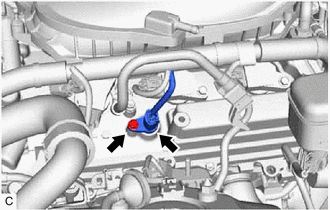
Disconnect the VVT sensor connector.
-
Remove the bolt and VVT sensor from the cylinder head cover sub-assembly LH.
-