КОРПУС ДРОССЕЛЬНОЙ ЗАСЛОНКИ УСТАНОВКА

PROCEDURE
-
INSTALL THROTTLE BODY GASKET
-
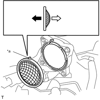
*a Protrusion 
Throttle Body with Motor Assembly Side 
Intake Air Surge Tank Assembly Side Install a new throttle body gasket onto the intake air surge tank assembly with the protrusion of the throttle body gasket oriented as shown in the illustration.
-
-
INSTALL THROTTLE BODY WITH MOTOR ASSEMBLY
-
Connect the No. 1 water by-pass hose and No. 2 water by-pass hose to the throttle body with motor assembly and slide the 2 clips to secure them.
-
Install the throttle body with motor assembly to the intake air surge tank assembly with the 4 bolts.
- Torque:
- 10 N*m { 102 kgf*cm, 7 ft.*lbf }
-
Connect the throttle body with motor assembly connector.
-
-
INSTALL AIR CLEANER CAP WITH AIR CLEANER HOSE
-
Connect the air cleaner cap with air cleaner hose to the throttle body with motor assembly.
-
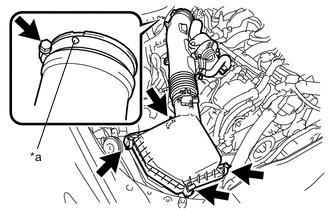
*a Protrusion Install the air cleaner cap with air cleaner hose with the 4 clamps.
-
Tighten the hose clamp.
- Torque:
- 4.0 N*m { 41 kgf*cm, 35 in.*lbf }
Note
Fit the protrusion on the air cleaner hose into the hole of the hose clamp on the throttle body with motor assembly side.
-
Connect the union to check valve hose to the air cleaner cap with air cleaner hose (for RHD).
-
Connect the No. 2 fuel vapor feed hose clamp to the air cleaner cap with air cleaner hose.
-
Connect the wire harness clamp to the air cleaner cap with air cleaner hose.
-
Connect the mass air flow meter sub-assembly connector.
-
-
CONNECT NO. 2 VENTILATION HOSE
-
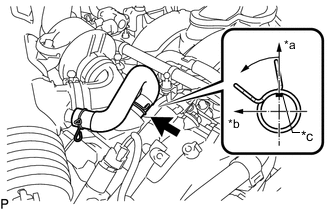
*a Top *b Front *c Paint Mark Connect the No. 2 ventilation hose to the cylinder head cover sub-assembly and slide the clip to secure it.
Tech Tips
Make sure the direction of the clip is as shown in the illustration.
-
-
INSTALL INTAKE AIR SOUND CREATOR
Tech Tips
Only perform this procedure when replacement of the intake air sound creator is necessary.
-
Connect the intake air sound creator to the air cleaner cap with air cleaner hose.
-
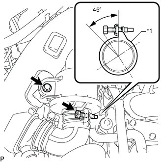
*1 Air Cleaner Hose Install the bolt and tighten the hose clamp.
- Torque:
- 5.0 N*m { 51 kgf*cm, 44 in.*lbf }
Tech Tips
Make sure the direction of the hose clamp is as shown in the illustration.
-
-
ADD ENGINE COOLANT
-
INSPECT FOR ENGINE COOLANT LEAK
-
INSTALL CENTER NO. 4 ENGINE UNDER COVER
-
INSTALL V-BANK COVER SUB-ASSEMBLY
-
PERFORM INITIALIZATION
Note
-
Be sure to perform this procedure after removing and reinstalling the throttle body with motor assembly or any throttle body with motor assembly components.
-
Perform the following procedure after replacing the throttle body with motor assembly or any throttle body with motor assembly components. The following procedure should also be performed if the throttle body with motor assembly is cleaned.
-
After turning the engine switch off, waiting time may be required before disconnecting the cable from the negative (-) battery terminal. Therefore, make sure to read the disconnecting the cable from the negative (-) battery terminal notice before proceeding with work.
-
Disconnect the cable from the negative (-) battery terminal. Wait at least 60 seconds and reconnect the cable.
Note
When disconnecting the cable, some systems need to be initialized after the cable is reconnected.
-
Connect the GTS to the DLC3 and clear the DTCs.
-
Turn the engine switch on (IG) without operating the accelerator pedal.
Note
If the accelerator pedal is operated, perform the above steps again.
-
Start the engine and check that the MIL is not illuminated. After the engine is warmed up, check that the idle speed is within the specified range with the A/C switch off.
Standard 600 to 700 rpm Note
-
Be sure to perform this step with all accessories off.
-
Make sure that the shift lever is in N or P.
-
-
Enter the following menus: Powertrain / Engine and ECT / Data List / Throttle Sensor Position.
Powertrain > Engine > Data ListTester Display Throttle Sensor Position -
Fully depress the accelerator pedal and check that the value is 60% or higher.
-
Perform a road test and confirm that there are no abnormalities.
-