AUTOMATIC HIGH BEAM SYSTEM TERMINALS OF ECU
-
CHECK INSTRUMENT PANEL JUNCTION BLOCK ASSEMBLY, MAIN BODY ECU (MULTIPLEX NETWORK BODY ECU)
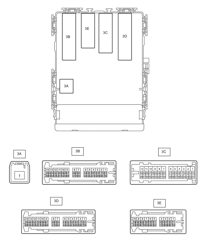
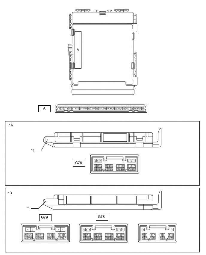
*A Main Body ECU (Multiplex Network Body ECU) with 1 connector *B Main Body ECU (Multiplex Network Body ECU) with 3 connectors *1 Main Body ECU (Multiplex Network Body ECU) - -
-
Remove the main body ECU (multiplex network body ECU) from the instrument panel junction block assembly.
-
Connect the instrument panel junction block assembly connectors.
-
Measure the voltage and resistance according to the value(s) in the table below.
Terminal No. (Symbol) Wiring Color Terminal Description Condition Specified Condition A-32 (IG) - Body ground - Ignition power supply Ignition switch ON 11 to 14 V*1
10.5 to 14 V*2
Ignition switch off Below 1 V A-30 (BECU) - Body ground - Battery power supply Always 11 to 14 V A-29 (ACC) - Body ground - ACC power supply Ignition switch ACC 11 to 14 V Ignition switch off Below 1 V A-11 (GND1) - Body ground - Ground Always Below 1 Ω *1: w/o Stop and Start System
*2: w/ Stop and Start System
If the result is not as specified, there may be a malfunction in the wire harness or instrument panel junction block assembly.
-
Install the main body ECU (multiplex network body ECU).
-
Measure the voltage and pulse according to the value(s) in the table below.
Terminal No. (Symbol) Wiring Color Terminal Description Condition Specified Condition 3B-54 (DIM) - Body ground LG - Body ground DIMMER relay drive output Headlight dimmer switch in high or high flash position Below 1 V Headlight dimmer switch not in high or high flash position 11 to 14 V G78-5 (HU) - Body ground Y - Body ground Headlight dimmer switch high signal input Headlight dimmer switch in high position Below 1 V Headlight dimmer switch in low position Pulse generation*1
11 to 14 V*2
G78-20 (CLTB) - G78-22 (CLTE) W - V Automatic light control sensor power supply output Ignition switch off Below 1 V Ignition switch ON
Headlight dimmer switch in AUTO position
11 to 14 V G78-21 (CLTS) - Body ground G - Body ground Automatic light control sensor signal input Ignition switch off Below 1 V Ignition switch ON
Headlight dimmer switch in AUTO position
Automatic light control sensor covered with a hand → Automatic light control sensor exposed to ambient light
Pulse generation (See waveform 1) G78-28 (A) - Body ground G - Body ground Headlight dimmer switch AUTO position signal input Headlight dimmer switch in AUTO position Below 1 V Headlight dimmer switch not in AUTO position Pulse generation*1
11 to 14 V*2
*1: Main Body ECU (multiplex network body ECU) with 3 Connectors
*2: Main Body ECU (multiplex network body ECU) with 1 Connectors
-
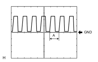
Waveform 1
Item Content Terminal No. (Symbol) G78-21 (CLTS) - Body ground Tool setting 5 V/DIV., 5 ms./DIV. Condition Ignition switch ON
Headlight dimmer switch in AUTO position
Automatic light control sensor covered with a hand → Automatic light control sensor exposed to ambient light
Tech Tips
If the ambient light becomes brighter, width A becomes narrower.
-
-
-
CHECK LANE DEPARTURE WARNING CAMERA
-
Check the lane departure warning camera.
-