AUTOMATIC HEADLIGHT BEAM LEVEL CONTROL SYSTEM LVL Terminal Circuit
DESCRIPTION
When terminals LVL and CG of the DLC3 are connected, the headlight leveling ECU initializes the height control sensor signal.
WIRING DIAGRAM
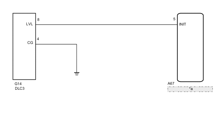
| *a | Headlight Leveling ECU Assembly |
CAUTION / NOTICE / HINT
Tech Tips
After replacing the headlight leveling ECU, initialization of the ECU is necessary.
PROCEDURE
-
CHECK HARNESS AND CONNECTOR (DLC3 - HEADLIGHT LEVELING ECU ASSEMBLY)
-
Disconnect the A67 headlight leveling ECU connector.
-
Measure the resistance according to the value(s) in the table below.
Standard Resistance Tester Connection Condition Specified Condition A67-5 (INIT) - G14-8 (LVL) Always Below 1 Ω A67-5 (INIT) - Body ground Always 10 kΩ or higher Result Proceed to OK NG
NG 
REPAIR OR REPLACE HARNESS OR CONNECTOR
OK 
-
-
CHECK HARNESS AND CONNECTOR (DLC3 - BODY GROUND)
-
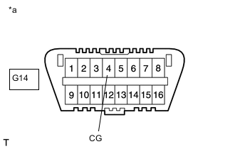
*a Front view of DLC3 Measure the resistance according to the value(s) in the table below.
Standard Resistance Tester Connection Condition Specified Condition G14-4 (CG) - Body ground Always Below 1 Ω Result Proceed to OK NG
OK
REPLACE HEADLIGHT LEVELING ECU ASSEMBLY Click here
NG
REPAIR OR REPLACE HARNESS OR CONNECTOR
-