LIGHTING SYSTEM Taillight Relay Circuit
DESCRIPTION
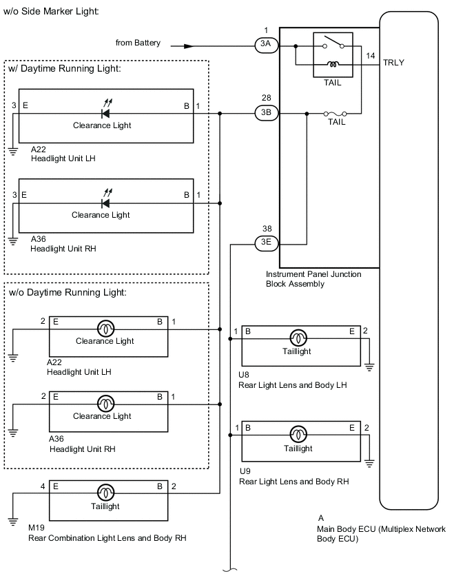
The main body ECU (multiplex network body ECU) receives headlight dimmer switch information signals and illuminates the clearance lights*1, parking light*2, taillights and license plate lights.
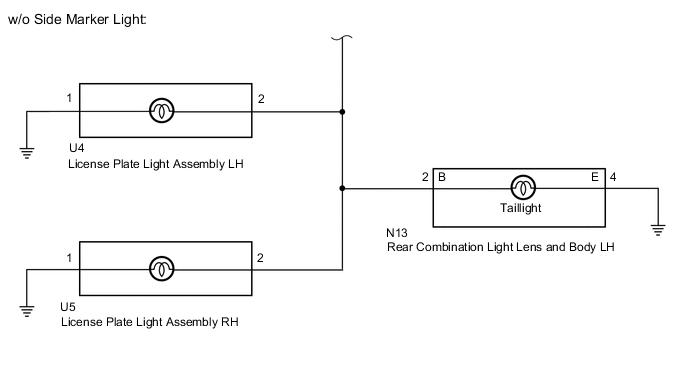
*1: w/o Side Marker Light
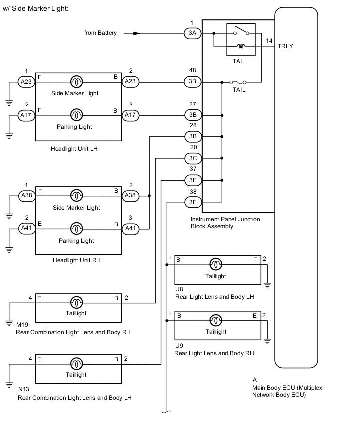
*2: w/ Side Marker Light
WIRING DIAGRAM
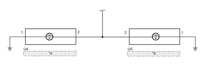
| *a | License Plate Light Assembly LH |
| *b | License Plate Light Assembly RH |
CAUTION / NOTICE / HINT
Note
-
Inspect the bulbs and fuses for circuits related to this system before performing the following inspection procedure.
-
When replacing the main body ECU (multiplex network body ECU), make sure to replace it with a new one.
PROCEDURE
-
PERFORM ACTIVE TEST USING GTS (TAILLIGHT RELAY)
-
Using the GTS, perform the Active Test.
Body Electrical > Main Body > Active TestTester Display Measurement Item Control Range Diagnostic Note Taillight Relay Taillight relay ON or OFF -
Body Electrical > Main Body > Active TestTester Display Taillight Relay Result Proceed to Taillights come on Taillights do not come on
Taillights come on 
REPLACE MAIN BODY ECU (MULTIPLEX NETWORK BODY ECU) for LHD: REPLACE MAIN BODY ECU (MULTIPLEX NETWORK BODY ECU) Click here
REPLACE MAIN BODY ECU (MULTIPLEX NETWORK BODY ECU) for RHD: REPLACE MAIN BODY ECU (MULTIPLEX NETWORK BODY ECU) Click hereTaillights do not come on 
-
-
CHECK HARNESS AND CONNECTOR (INSTRUMENT PANEL JUNCTION BLOCK ASSEMBLY - BATTERY)
-
Disconnect the instrument panel junction block assembly connector.
-
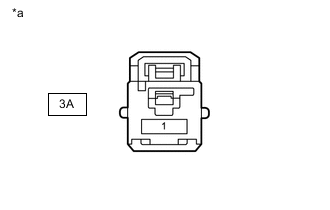
*a Front view of wire harness connector
(to Instrument Panel Junction Block Assembly)
Measure the voltage according to the value(s) in the table below.
Standard Voltage Tester Connection Condition Specified Condition 3A-1 - Body ground Always 11 to 14 V Result Proceed to OK NG
NG
REPAIR OR REPLACE HARNESS OR CONNECTOR
OK
-
-
INSPECT INSTRUMENT PANEL JUNCTION BLOCK ASSEMBLY (TAIL RELAY)
-
w/o Side Marker Light:
-
Remove the instrument panel junction block assembly.
for LHD:
for RHD:
-
Remove the main body ECU (multiplex network body ECU) from the instrument panel junction block assembly.
for LHD:
for RHD:
-
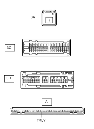
Measure the resistance according to the value(s) in the table below.
Standard Resistance Tester Connection Condition Specified Condition 3A-1 - 3B-28 Battery voltage applied between terminals 3A-1 and A-14 (TRLY) Below 1 Ω Battery voltage not applied between terminals 3A-1 and A-14 (TRLY) 10 kΩ or higher 3A-1 - 3E-38 Battery voltage applied between terminals 3A-1 and A-14 (TRLY) Below 1 Ω Battery voltage not applied between terminals 3A-1 and A-14 (TRLY) 10 kΩ or higher
-
-
w/ Side Marker Light
-
Remove the instrument panel junction block assembly.
-
Remove the main body ECU (multiplex network body ECU) from the instrument panel junction block assembly.
-
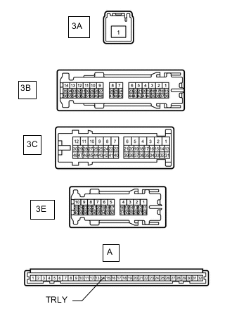
Measure the resistance according to the value(s) in the table below.
Standard Resistance Tester Connection Condition Specified Condition 3A-1 - 3B-48 Battery voltage applied between terminals 3A-1 and A-14 (TRLY) Below 1 Ω Battery voltage not applied between terminals 3A-1 and A-14 (TRLY) 10 kΩ or higher 3A-1 - 3B-27 Battery voltage applied between terminals 3A-1 and A-14 (TRLY) Below 1 Ω Battery voltage not applied between terminals 3A-1 and A-14 (TRLY) 10 kΩ or higher 3A-1 - 3B-28 Battery voltage applied between terminals 3A-1 and A-14 (TRLY) Below 1 Ω Battery voltage not applied between terminals 3A-1 and A-14 (TRLY) 10 kΩ or higher 3A-1 - 3C-20 Battery voltage applied between terminals 3A-1 and A-14 (TRLY) Below 1 Ω Battery voltage not applied between terminals 3A-1 and A-14 (TRLY) 10 kΩ or higher 3A-1 - 3E-37 Battery voltage applied between terminals 3A-1 and A-14 (TRLY) Below 1 Ω Battery voltage not applied between terminals 3A-1 and A-14 (TRLY) 10 kΩ or higher 3A-1 - 3E-38 Battery voltage applied between terminals 3A-1 and A-14 (TRLY) Below 1 Ω Battery voltage not applied between terminals 3A-1 and A-14 (TRLY) 10 kΩ or higher
Result Proceed to OK NG -
OK
PROCEED TO NEXT SUSPECTED AREA SHOWN IN PROBLEM SYMPTOMS TABLE Click here
NG
REPLACE INSTRUMENT PANEL JUNCTION BLOCK ASSEMBLY for LHD: REPLACE INSTRUMENT PANEL JUNCTION BLOCK ASSEMBLY Click here
REPLACE INSTRUMENT PANEL JUNCTION BLOCK ASSEMBLY for RHD: REPLACE INSTRUMENT PANEL JUNCTION BLOCK ASSEMBLY Click here -