LIGHTING SYSTEM Headlight Relay Circuit
DESCRIPTION
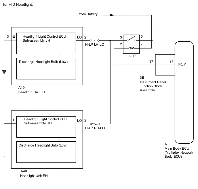
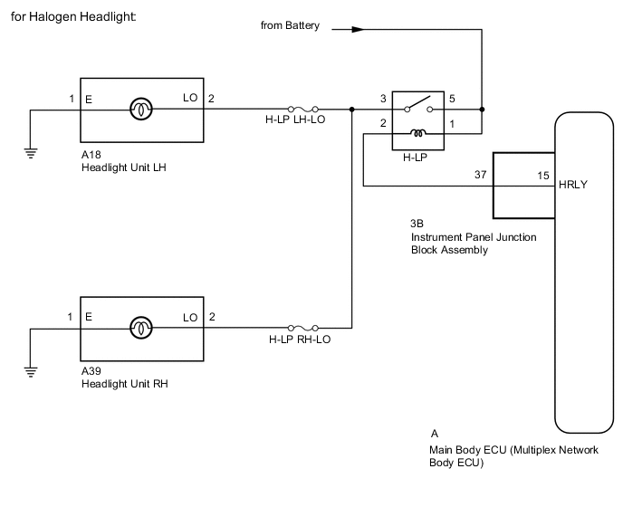
The main body ECU (multiplex network body ECU) receives headlight dimmer switch information signals and illuminates the low beam headlights.
WIRING DIAGRAM
CAUTION / NOTICE / HINT
Note
-
Inspect the bulbs and fuses for circuits related to this system before performing the following inspection procedure.
-
When replacing the main body ECU (multiplex network body ECU), make sure to replace it with a new one.
PROCEDURE
-
PERFORM ACTIVE TEST USING GTS (H-LP RELAY)
-
Using the GTS, perform the Active Test.
Body Electrical > Main Body > Active TestTester Display Measurement Item Control Range Diagnostic Note Headlight Relay Low beam headlight relay ON or OFF -
Body Electrical > Main Body > Active TestTester Display Headlight Relay OK Headlight relay operates (low beam headlights come on). Result Proceed to OK NG
OK 
REPLACE MAIN BODY ECU (MULTIPLEX NETWORK BODY ECU) for LHD: REPLACE MAIN BODY ECU (MULTIPLEX NETWORK BODY ECU) Click here
REPLACE MAIN BODY ECU (MULTIPLEX NETWORK BODY ECU) for RHD: REPLACE MAIN BODY ECU (MULTIPLEX NETWORK BODY ECU) Click hereNG 
-
-
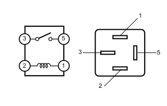
INSPECT HEADLIGHT RELAY (H-LP)
-
Remove the headlight relay from the No. 1 engine room relay block and junction block assembly.
-
Measure the resistance according to the value(s) in the table below.
Standard Resistance Tester Connection Condition Specified Condition 3 - 5 Battery voltage applied between terminals 1 and 2 Below 1 Ω 3 - 5 Battery voltage not applied between terminals 1 and 2 10 kΩ or higher Result Proceed to OK NG
NG
REPLACE HEADLIGHT RELAY (H-LP)
OK
-
-
CHECK HARNESS AND CONNECTOR (HEADLIGHT RELAY [H-LP] - BATTERY)
-
Remove the headlight relay from the No. 1 engine room relay block and junction block assembly.
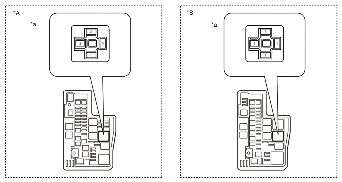
*A w/o Side Marker Light *B w/ Side Marker Light *a Front view of wire harness connector
(to Headlight Relay)
- - -
Measure the voltage according to the value(s) in the table below.
Standard Voltage Tester Connection Condition Specified Condition Headlight relay terminal 5 - Body ground Always 11 to 14 V Headlight relay terminal 1 - Body ground Result Proceed to OK NG
NG
REPAIR OR REPLACE HARNESS OR CONNECTOR
OK
-
-
CHECK HARNESS AND CONNECTOR (HEADLIGHT RELAY [H-LP] - INSTRUMENT PANEL JUNCTION BLOCK ASSEMBLY)
-
Remove the headlight relay from the No. 1 engine room relay block and junction block assembly.
-
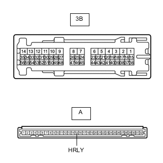
Disconnect the 3B instrument panel junction block assembly connector.
-
Measure the resistance according to the value(s) in the table below.
Standard Resistance Tester Connection Condition Specified Condition Headlight relay terminal 2 - 3B-37 Always Below 1 Ω 3B-37 - Body ground Always 10 kΩ or higher Result Proceed to OK NG
NG
REPAIR OR REPLACE HARNESS OR CONNECTOR
OK
-
-
INSPECT INSTRUMENT PANEL JUNCTION BLOCK ASSEMBLY
-
Remove the instrument panel junction block assembly.
for LHD:
for RHD:
-
Remove the main body ECU (multiplex network body ECU) from the instrument panel junction block assembly.
for LHD:
for RHD:
-
Measure the resistance according to the value(s) in the table below.
Standard Resistance Tester Connection Condition Specified Condition A-15 (HRLY) - 3B-37 Always Below 1 Ω Result Proceed to OK NG
OK
PROCEED TO NEXT SUSPECTED AREA SHOWN IN PROBLEM SYMPTOMS TABLE Click here
NG
REPLACE INSTRUMENT PANEL JUNCTION BLOCK ASSEMBLY for LHD: REPLACE INSTRUMENT PANEL JUNCTION BLOCK ASSEMBLY Click here
REPLACE INSTRUMENT PANEL JUNCTION BLOCK ASSEMBLY for RHD: REPLACE INSTRUMENT PANEL JUNCTION BLOCK ASSEMBLY Click here -