LIGHTING SYSTEM, Diagnostic DTC:B1244
| DTC Code | DTC Name |
|---|---|
| B1244 | Light Sensor Circuit Malfunction |
DESCRIPTION
The automatic light control sensor detects ambient light, converts it into an electrical signal and outputs it to the main body ECU (multiplex network body ECU). The main body ECU (multiplex network body ECU) turns the headlights and taillights on or off according to the signal.
| DTC No. | Detection Item | DTC Detection Condition | Trouble Area |
|---|---|---|---|
| B1244 | Light Sensor Circuit Malfunction |
|
|
WIRING DIAGRAM
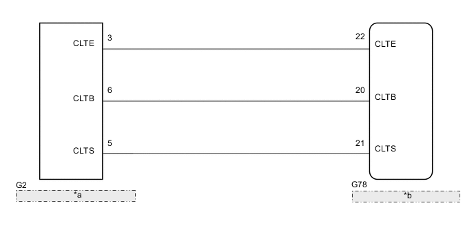
| *a | Automatic Light Control Sensor |
| *b | Main Body ECU (Multiplex Network Body ECU) |
CAUTION / NOTICE / HINT
Note
When replacing the main body ECU (multiplex network body ECU), make sure to replace it with a new one.
PROCEDURE
-
CLEAR DTC
-
Clear the DTCs.
Body Electrical > Main Body > Clear DTCsResult Proceed to NEXT
NEXT 
-
-
CHECK FOR DTC
-
Clear the DTCs.
Body Electrical > Main Body > Clear DTCsResult Proceed to DTC B1244 output does not occur DTC B1244 output occur
DTC B1244 output does not occur 
USE SIMULATION METHOD TO CHECK Click here
DTC B1244 output occur
-
-
READ VALUE USING GTS (AUTOMATIC LIGHT CONTROL SENSOR)
-
Using the GTS, read the Data List.
Body Electrical > Main Body > Data ListTester Display Measurement Item Range Normal Condition Diagnostic Note Illumination Rate Info Illumination rate information 0 ms. to 2162.65 ms. Value output according to ambient light levels -
Body Electrical > Main Body > Data ListTester Display Illumination Rate Info OK The display is as specified in the normal condition column. Result Proceed to OK NG
OK
REPLACE MAIN BODY ECU (MULTIPLEX NETWORK BODY ECU) for LHD: REPLACE MAIN BODY ECU (MULTIPLEX NETWORK BODY ECU) Click here
REPLACE MAIN BODY ECU (MULTIPLEX NETWORK BODY ECU) for RHD REPLACE MAIN BODY ECU (MULTIPLEX NETWORK BODY ECU) Click hereNG
-
-
CHECK HARNESS AND CONNECTOR (MAIN BODY ECU - AUTOMATIC LIGHT CONTROL SENSOR)
-
Disconnect the G78 main body ECU (multiplex network body ECU) connector.
-
Disconnect the G2 automatic light control sensor connector.
-
Measure the resistance according to the value(s) in the table below.
Standard Resistance Tester Connection Condition Specified Condition G78-22 (CLTE) - G2-3 (CLTE) Always Below 1 Ω G78-21 (CLTS) - G2-5 (CLTS) Always Below 1 Ω G78-20 (CLTB) - G2-6 (CLTB) Always Below 1 Ω G78-22 (CLTE) - Body ground Always 10 kΩ or higher G78-21 (CLTS) - Body ground Always 10 kΩ or higher G78-20 (CLTB) - Body ground Always 10 kΩ or higher Result Proceed to OK NG
NG
REPAIR OR REPLACE HARNESS OR CONNECTOR
OK
-
-
CHECK MAIN BODY ECU (MULTIPLEX NETWORK BODY ECU)
-
*a Component with harness connected
(Main Body ECU [Multiplex Network Body ECU])
Remove the instrument panel junction block assembly and main body ECU (multiplex network body ECU) as a unit with the connectors still connected.
for LHD:
for RHD:
-
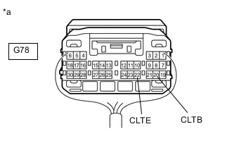
Measure the voltage according to the value(s) in the table below.
Standard Voltage Tester Connection Switch Condition Specified Condition G78-20 (CLTB) - G78-22 (CLTE) Ignition switch off Below 1 V Ignition switch ON 11 to 14 V Result Proceed to OK NG
NG
REPLACE MAIN BODY ECU (MULTIPLEX NETWORK BODY ECU) for LHD: REPLACE MAIN BODY ECU (MULTIPLEX NETWORK BODY ECU) Click here
REPLACE MAIN BODY ECU (MULTIPLEX NETWORK BODY ECU) for RHD: REPLACE MAIN BODY ECU (MULTIPLEX NETWORK BODY ECU) Click hereOK
-
-
CHECK AUTOMATIC LIGHT CONTROL SENSOR
-
Check the automatic light control sensor.
Result Proceed to OK NG
OK
REPLACE MAIN BODY ECU (MULTIPLEX NETWORK BODY ECU) for LHD: REPLACE MAIN BODY ECU (MULTIPLEX NETWORK BODY ECU) Click here
REPLACE MAIN BODY ECU (MULTIPLEX NETWORK BODY ECU) for RHD: REPLACE MAIN BODY ECU (MULTIPLEX NETWORK BODY ECU) Click hereNG
REPLACE AUTOMATIC LIGHT CONTROL SENSOR Click here
-