BACK DOOR CLOSER SYSTEM TERMINALS OF ECU
-
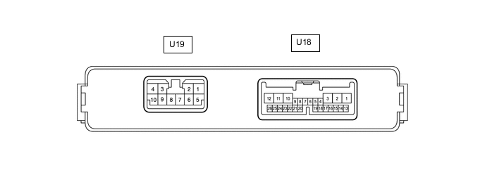
CHECK MULTIPLEX NETWORK DOOR ECU
-
Disconnect the U18 and U19 multiplex network door ECU connectors.
-
Measure the voltage and resistance according to the value(s) in the table below.
Terminal No. (Symbol) Wiring Color Terminal Description Condition Specified Condition U18-1 (ECUB) - Body ground W - Body ground Battery power supply Always 11 to 14 V U18-7 (IG) - Body ground W - Body ground IG power supply Ignition switch ON 11 to 14 V U18-7 (IG) - Body ground W - Body ground IG power supply Ignition switch off Below 1 V U19-8 (B) - Body ground W - Body ground Battery power supply Always 11 to 14 V U19-7 (GND) - Body ground W-B - Body ground Body ground Always Below 1 Ω -
Reconnect the U18 and U19 multiplex network door ECU connectors.
-
Measure the voltage according to the value(s) in the table below.
Terminal No. (Symbol) Wiring Color Terminal Description Condition Specified Condition U19-10 (DC+) - U19-9 (DC-) B - R Back door lock assembly (back door lock motor) circuit Back door lock motor operating 11 to 14 V U19-10 (DC+) - U19-9 (DC-) B - R Back door lock assembly (back door lock motor) circuit Back door lock motor not operating Below 1 V U18-19 (FUL) - Body ground W - Body ground Back door lock assembly (back door courtesy switch) signal circuit Back door closed → open 11 to 14 V → Below 1 V U18-21 (HAF) - Body ground G - Body ground Back door lock assembly (latch switch) signal circuit Back door closed → fully open 11 to 14 V → Below 1 V U18-24 (POS) - Body ground GR - Body ground Back door lock assembly (sector switch) signal circuit Back door open → Back door closer operates → Back door closed Below 1 V → 11 to 14 V → Below 1 V
-
-
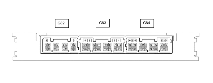
CHECK CERTIFICATION ECU (SMART KEY ECU ASSEMBLY) (w/ Entry and Start System)
-
Disconnect the G82 and G84 certification ECU (smart key ECU assembly) connectors.
-
Measure the voltage and resistance according to the value(s) in the table below.
Terminal No. (Symbol) Wiring Color Terminal Description Condition Specified Condition G82-2 (+B) - Body ground W - Body ground Battery power supply Always 11 to 14 V G82-10 (CUTB) - Body ground P - Body ground Battery power supply Always 11 to 14 V G84-5 (IG) - Body ground LG - Body ground IG power supply Ignition switch ON 11 to 14 V G84-5 (IG) - Body ground LG - Body ground IG power supply Ignition switch off Below 1 V G82-11 (E) - Body ground BR - Body ground Body ground Always Below 1 Ω -
Reconnect the G82 and G84 certification ECU (smart key ECU assembly) connectors.
-
Measure the voltage according to the value(s) in the table below.
Terminal No. (Symbol) Wiring Color Terminal Description Condition Specified Condition G83-27 (TSW5) - Body ground Y - Body ground Back door opener switch assembly signal Back door opener switch assembly off Pulse generation G83-27 (TSW5) - Body ground Y - Body ground Back door opener switch assembly signal Back door opener switch assembly on Below 1 V
-
-
CHECK MAIN BODY ECU (MULTIPLEX NETWORK BODY ECU) AND INSTRUMENT PANEL JUNCTION BLOCK ASSEMBLY

*1 Main Body ECU (Multiplex Network Body ECU) - -
-
Remove the main body ECU (multiplex network body ECU).
for LHD: Click here
for RHD: Click here
-
Connect the instrument panel junction block assembly connectors.
-
Measure the voltage and resistance according to the value(s) in the table below.
Terminal No. (Symbol) Wiring Color Terminal Description Condition Specified Condition A-30 (BECU) -Body ground None - Body ground Battery power supply Always 11 to 14 V A-29 (ACC) -Body ground None - Body ground ACC power supply Ignition switch ACC 11 to 14 V A-29 (ACC) -Body ground None - Body ground ACC power supply Ignition switch off Below 1 V A-32 (IG) - Body ground None - Body ground IG power supply Ignition switch ON 11 to 14 V A-32 (IG) - Body ground None - Body ground IG power supply Ignition switch off Below 1 V A-11 (GND1) - Body ground None - Body ground Body ground Always Below 1 Ω -
Install the main body ECU (multiplex network body ECU).
for LHD : Click here
for RHD : Click here
-
Measure the voltage according to the value(s) in the table below.
Terminal No. (Symbol) Wiring Color Terminal Description Condition Specified Condition G78-23 (BDSU) - Body ground* R - Body ground Back door opener switch assembly signal Back door opener switch assembly off Pulse generation G78-23 (BDSU) - Body ground* R - Body ground Back door opener switch assembly signal Back door opener switch assembly on Below 1 V *: w/o Entry and Start System
-