BACK DOOR CLOSER SYSTEM SYSTEM DESCRIPTION
-
BACK DOOR CLOSER SYSTEM DESCRIPTION
-
Operating any back door opener switch assembly when the back door is fully closed inputs a request signal to the multiplex network door ECU. The multiplex network door ECU outputs a "latch release" command to the back door lock assembly in response to the input.
-
The latch can be released only when the back door is unlocked.
-
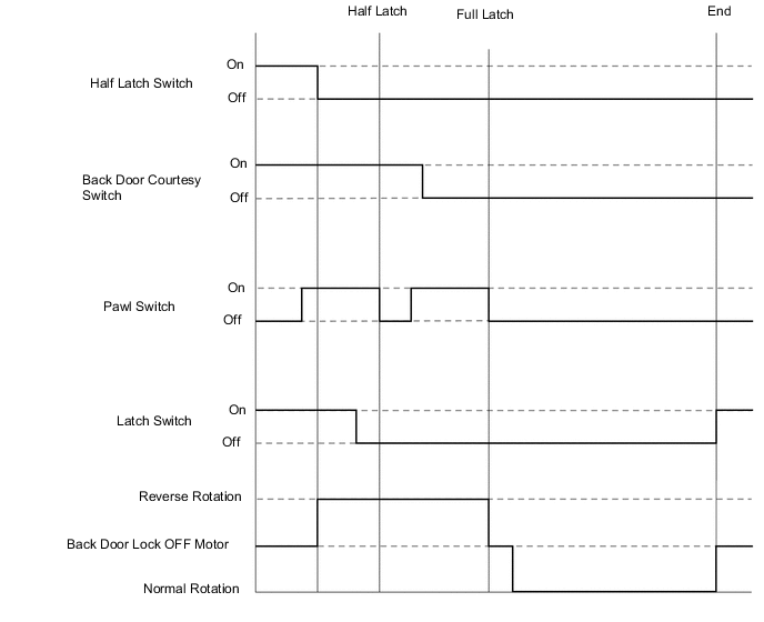
4 switches are built into the back door lock assembly, and the multiplex network door ECU monitors each switch status. The multiplex network door ECU controls latch "release/close" operations in response to the inputs from each switch.
Switch Function Back door courtesy switch This switch detects that the latch is fully closed and outputs a signal to the multiplex network door ECU. Latch switch This switch detects the ajar position of the latch and the fully closed position of the latch due to the closer operation and outputs a signal to the multiplex network door ECU. Sector switch This switch detects the neutral position (initial position) of the back door closer motor and sector gear and outputs it to the multiplex network door ECU. Pawl switch This switch detects that the latch is opened and then closed and outputs a signal to the multiplex network door ECU.
-
-
FUNCTION OF MAIN COMPONENTS
Component Function Multiplex network door ECU The multiplex network door ECU controls the back door closer system in accordance with the signals received from the back door lock assembly. Back door lock assembly Receives an operation signal from the multiplex network door ECU to open/close the back door. -
CONSTRUCTION AND OPERATION
-
Closing Operation
-