SLIDING ROOF SYSTEM TERMINALS OF ECU
-
CHECK SLIDING ROOF DRIVE GEAR SUB-ASSEMBLY (SLIDING ROOF ECU)
-
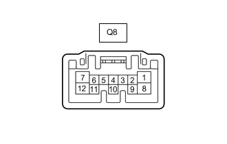
Disconnect the Q8 sliding roof drive gear sub-assembly (sliding roof ECU) connector.
-
Measure the resistance and voltage according to the value(s) in the table below.
Tech Tips
Measure the values on the wire harness side with the connector disconnected.
Tester Connection Wiring Color Terminal Description Condition Specified Condition Q8-1 (IG) - Body ground B - W-B IG power supply Ignition switch off Below 1 V Q8-1 (IG) - Body ground B - W-B IG power supply Ignition switch ON 11 to 14 V Q8-8 (B) - Body ground L - W-B Battery power supply Always 11 to 14 V Q8-12 (E) - Body ground W-B - Body ground Ground Always Below 1 Ω -
Reconnect the Q8 sliding roof drive gear sub-assembly (sliding roof ECU) connector.
-
Measure the voltage according to the value(s) in the table below.
Tester Connection Wiring Color Terminal Description Condition Specified Condition Q8-7 (OPN) - Body ground R - W-B Sliding roof motor open Ignition switch ON, OPEN switch on Below 1 V Q8-7 (OPN) - Body ground R - W-B Sliding roof motor open Ignition switch ON, OPEN switch off 11 to 14 V Q8-5 (CLS) - Body ground B - W-B Sliding roof motor close Ignition switch ON, CLOSE switch on Below 1 V Q8-5 (CLS) - Body ground B - W-B Sliding roof motor close Ignition switch ON, CLOSE switch off 11 to 14 V Q8-4 (UP) - Body ground G - W-B Sliding roof motor up Ignition switch ON, UP switch on Below 1 V Q8-4 (UP) - Body ground G - W-B Sliding roof motor up Ignition switch ON, UP switch off 11 to 14 V Q8-6 (DWN) - Body ground GR - W-B Sliding roof motor down Ignition switch ON, DOWN switch on Below 1 V Q8-6 (DWN) - Body ground GR - W-B Sliding roof motor down Ignition switch ON, DOWN switch off 11 to 14 V Q8-11 (MPX1) V LIN communication line - -
-