HEATED WINDSHIELD DEFROSTER SYSTEM TERMINALS OF ECU
-
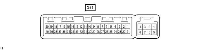
CHECK AIR CONDITIONING AMPLIFIER ASSEMBLY (for Automatic Air Conditioning System)
-
Disconnect the G81 air conditioning amplifier assembly connector.
-
Measure the voltage and resistance according to the value(s) in the table below.
Tech Tips
Measure the values on the wire harness side with the connector disconnected.
Tester Connection Wiring Color Terminal Description Condition Specified Condition G81-1 (IG+) - G81-14 (GND) GR - W-B Power source (IG) Ignition switch ON 11 to 14 V G81-1 (IG+) - G81-14 (GND) GR - W-B Power source (IG) Ignition switch off Below 1 V G81-21 (B) - G81-14 (GND) GR - W-B Power source (+B) Always 11 to 14 V G81-14 (GND) - Body ground W-B - Body ground Ground Always Below 1 Ω -
Reconnect the G81 air conditioning amplifier assembly connector.
-
Measure the voltage and check for pulses according to the value(s) in the table below.
Tester Connection Wiring Color Terminal Description Condition Specified Condition G81-19 (FDEF) - G81-14 (GND) V - W-B Heated windshield defroster signal Ignition switch ON, front window deicer switch off 11 to 14 V G81-19 (FDEF) - G81-14 (GND) V - W-B Heated windshield defroster signal Ignition switch ON, front window deicer switch on Below 1 V G81-37 (LIN1) - G81-14 (GND) B - W-B LIN communication line Ignition switch ON Pulse generation
-