ROOF HEADLINING REASSEMBLY
PROCEDURE
-
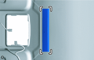
INSTALL NO. 4 ROOF HEADLINING SUPPORT (w/ Roof Headlining Support, w/ Sliding Roof)
-

Marking 
Peeling Paper Align the No. 4 roof headlining support with the marking on the roof headlining and install the No.4 roof headlining support to the position shown inthe illustration using adhesive or double-sided tape.
Note
If replacing a new No. 4 roof headlining support:
At this time, do not remove the peeling paper from the No. 4 roof headlining support.
-
-
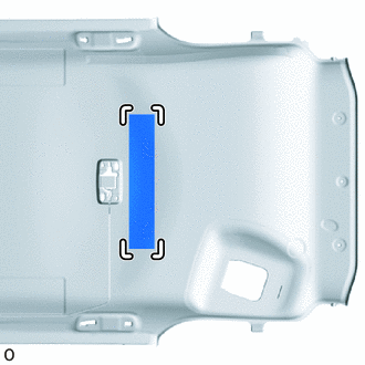
INSTALL NO. 3 ROOF HEADLINING SUPPORT (w/ Roof Headlining Support, w/ Sliding Roof)
Tech Tips
Use the same procedure described for the No. 4 roof headlining support.
-
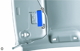
INSTALL ROOF HEADLINING SUPPORT (w/ Roof Headlining Support)
-
Marking w/o Sliding Roof:
Align the No. 2 roof headlining support with the marking on the roof headlining and install the No.2 roof headlining support to the position shown in the illustration using adhesive or double-sided tape.
-
Marking Peeling Paper w/ Sliding Roof:
Align the No. 2 roof headlining support with the marking on the roof headlining and install the No.2 roof headlining support to the position shown in the illustration using adhesive or double-sided tape.
Note
If replacing a new No. 2 roof headlining support:
At this time, do not remove the peeling paper from the No. 2 roof headlining support.
-
-
INSTALL NO. 2 ROOF HEADLINING SUPPORT (w/ Roof Headlining Support)
Tech Tips
Use the same procedure described for the No. 2 roof headlining support.
-
INSTALL NO. 2 ANTENNA CORD SUB-ASSEMBLY
-
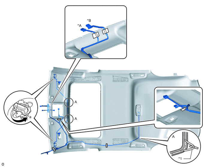
INSTALL NO. 1 ROOF WIRE
-
w/o Roof Headlining Support, w/o Sliding Roof:
-
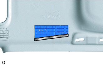
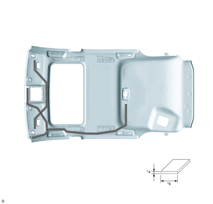
Apply new double-sided tape as shown in the illustration.
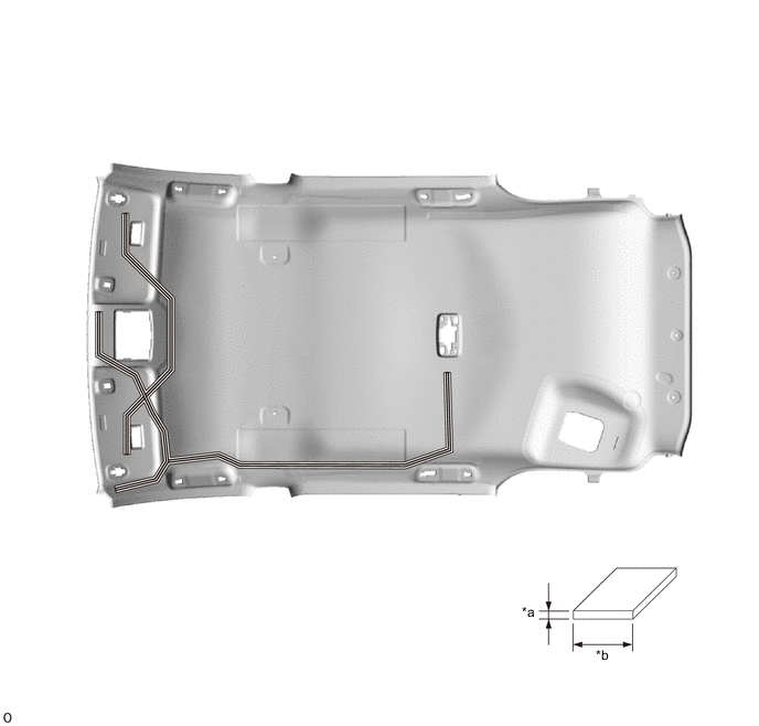
*a 1 mm (0.0394 in.) *b 15 mm (0.590 in.) Double-sided Tape - - -
Attach the No. 1 roof wire to the double-sided tape.
-
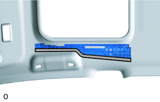
Apply new one-sided tape.
-
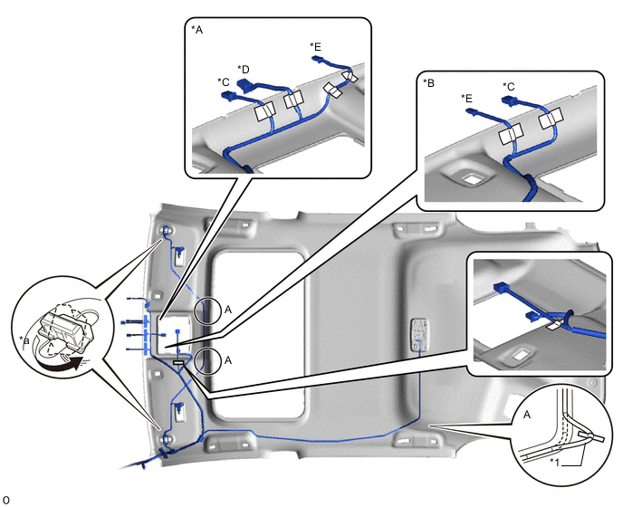
Turn the 2 connectors approximately 90° clockwise to connect them.
-
If any slack forms, take up the slack in the areas A shown in the illustration.
Note
Secure any wire that protrudes from the double-sided tape with one-sided tape.
*A for LHD *B for RHD *C w/ EC Mirror *D w/ Lane Departure Alert System *E w/ Rain Sensor - - *1 No. 1 Roof Wire - - *a 90° - - One-sided Tape Double-sided Tape -
Check that the No. 1 roof wire is not twisted, raised, or protruding in any way.
-
-
w/ Roof Headlining Support, w/o Sliding Roof:
-
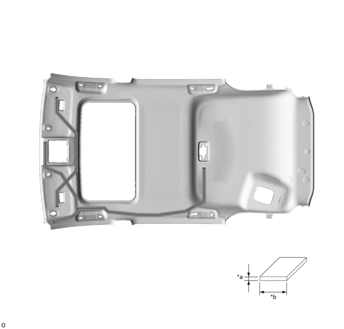
Apply new double-sided tape as shown in the illustration.
*a 1 mm (0.0394 in.) *b 15 mm (0.590 in.) Double-sided Tape - - -
Attach the No. 1 roof wire to the double-sided tape.
-
Apply new one-sided tape.
-
Turn the 2 connectors approximately 90° clockwise to connect them.
-
If any slack forms, take up the slack in the areas A shown in the illustration.
Note
Secure any wire that protrudes from the double-sided tape with one-sided tape.
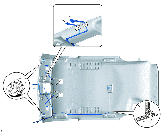
*A w/ EC Mirror *B w/ Lane Departure Alert System *1 No. 1 Roof Wire - - *a 90° - - One-sided Tape Double-sided Tape -
Check that the No. 1 roof wire is not twisted, raised, or protruding in any way.
-
-
w/o Roof Headlining Support, w/ Sliding Roof:
-
Apply new double-sided tape as shown in the illustration.
*a 1 mm (0.0394 in.) *b 15 mm (0.590 in.) Double-sided Tape - - -
Attach the No. 1 roof wire to the double-sided tape.
-
Apply new one-sided tape.
-
Turn the 2 connectors approximately 90° clockwise to connect them.
-
If any slack forms, take up the slack in the areas A shown in the illustration.
Note
Secure any wire that protrudes from the double-sided tape with one-sided tape.
*A for LHD *B for RHD *C w/ EC Mirror *D w/ Lane Departure Alert System *E w/ Rain Sensor - - *1 No. 1 Roof Wire - - *a 90° - - One-sided Tape Double-sided Tape -
Check that the No. 1 roof wire is not twisted, raised, or protruding in any way.
-
-
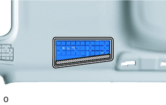
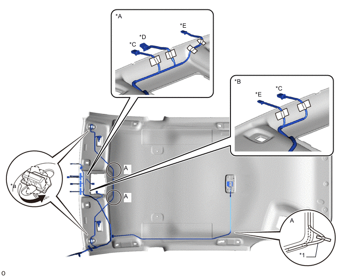
w/ Roof Headlining Support, w/ Sliding Roof:
-
Double-sided Tape If reusing the No. 4 roof headlining support:
Apply new double-sided tape as shown in the illustration.
-
If replacing the No. 4 roof headlining support:
Remove the peeling paper from the No. 4 roof headlining support.
-
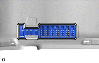
Double-sided Tape If reusing the No. 2 roof headlining support:
Apply new double-sided tape as shown in the illustration.
-
If replacing the No. 2 roof headlining support:
Remove the peeling paper from the No. 2 roof headlining support.
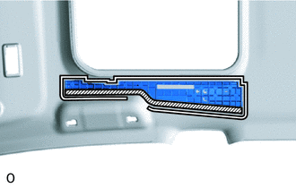
-
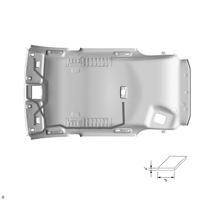
Apply new double-sided tape as shown in the illustration.
*a 1 mm (0.0394 in.) *b 15 mm (0.590 in.) Double-sided Tape - - -
Attach the No. 1 roof wire to the double-sided tape.
-
Apply new one-sided tape.
-
Turn the 2 connectors approximately 90° clockwise to connect them.
-
If any slack forms, take up the slack in the areas A shown in the illustration.
Note
Secure any wire that protrudes from the double-sided tape with one-sided tape.
*A w/ EC Mirror *B w/ Lane Departure Alert System *1 No. 1 Roof Wire - - *a 90° - - One-sided Tape Double-sided Tape -
Check that the No. 1 roof wire is not twisted, raised, or protruding in any way.
-
-
-
INSTALL VANITY LIGHT ASSEMBLY LH
-
Attach the claw to install the vanity light assembly LH.
-
Attach the 2 claws to connect the bulb holder to the vanity light assembly LH.
-
-
INSTALL VANITY LIGHT ASSEMBLY RH
Tech Tips
Use the same procedure described for the LH side.
-
INSTALL NO. 2 ROOF HEADLINING PAD (w/o Roof Headlining Support, for Cold Area)
-
Remove the peeling paper from a new No. 2 roof headlining pad.
-
Silencer Marking Align the No. 2 roof headlining pad end with the silencer markings on the roof headlining and install the No. 2 roof headlining pad end as shown in the illustration.
-
-
INSTALL NO. 2 ROOF HEADLINING PAD (w/ Roof Headlining Support)
-
Remove the peeling paper from a new No. 2 roof headlining pad.
-
Silencer Marking Align the No. 2 roof headlining pad end with the silencer markings on the roof headlining and install the No. 2 roof headlining pad end as shown in the illustration.
-
-
INSTALL ROOF HEADLINING PAD (w/o Roof Headlining Support, for Cold Area)
Tech Tips
Use the same procedure for both roof headlining pads.
-
Remove the peeling paper from a new roof headlining pad.
-
Silencer Marking Align the roof headlining pad with the silencer markings on the roof headlining and install the roof headlining pad as shown in the illustration.
-
-
INSTALL ROOF HEADLINING PAD (w/ Roof Headlining Support)
Tech Tips
Use the same procedure for both roof headlining pads.
-
Remove the peeling paper from a new roof headlining pad.
-
Silencer Marking Align the roof headlining pad with the silencer markings on the roof headlining and install the roof headlining pad as shown in the illustration.
-
-
INSTALL NO. 3 ROOF SILENCER PAD
-
Remove the peeling paper from a new No. 3 roof silencer pad.
-
Silencer Marking Align the No. 3 roof silencer pad with the silencer markings on the roof headlining and install the No. 3 roof silencer pad as shown in the illustration.
-
-
INSTALL NO. 1 ROOF SILENCER PAD (w/o Sliding Roof)
-
Remove the peeling paper from 5 new No. 1 roof silencer pads.
-
Align the No. 1 roof silencer pads with the silencer markings on the roof headlining and install the 5 No. 1 roof silencer pads as shown in the illustration.
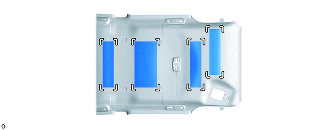
Silencer Marking - -
-
-
INSTALL NO. 1 ROOF SILENCER PAD (w/ Sliding Roof)
-
Remove the peeling paper from 2 new No. 1 roof silencer pads.
-
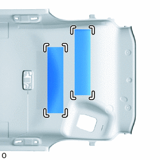
Silencer Marking Align the No. 1 roof silencer pads with the silencer markings on the roof headlining and install the 2 No. 1 roof silencer pads as shown in the illustration.
-
-
INSTALL ROOF HEADLINING PAD RH (w/ Roof Headlining Support)
-
Remove the peeling paper from a new roof headlining pad RH.
-
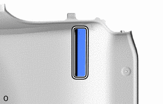
Silencer Marking Align the roof headlining pad RH end with the silencer markings on the roof headlining and install the roof headlining pad RH end as shown in the illustration.
-
-
INSTALL CENTER ROOF HEADLINING PAD
-
Remove the 2 peeling papers from 2 new center roof headlining pads.
-
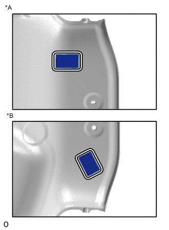
*A for RH Side *B for LH Side Silencer Marking Align the 2 center roof headlining pads end with the silencer markings on the roof headlining and install the 2 center roof headlining pads end as shown in the illustration.
-