LOWER INSTRUMENT PANEL INSTALLATION
CAUTION / NOTICE / HINT
Tech Tips
-
Use the same procedure for RHD and LHD vehicles.
-
The procedure listed below is for LHD vehicles.
-
A bolt without a torque specification is shown in the standard bolt chart.
PROCEDURE
-
INSTALL LOWER INSTRUMENT PANEL (for LHD)
-
Install the lower instrument panel with the bolt <G> and 2 bolts <C> or <D> and 6 bolts <E> or <F>.
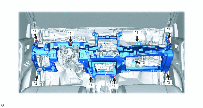
*1 Bolt <E> or <F> *2 Bolt <C> or <D> *3 Bolt <G> - - -
Attach the 2 claws to connect the cooler thermistor.
-
Attach the 2 claws to connect the DLC3.
-
Attach the claw to connect the hood lock control lever.
-
Connect each connector and attach each wire harness clamp.
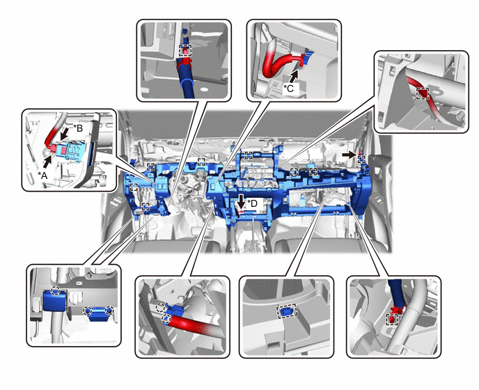
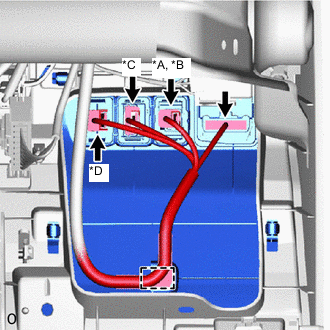
*A for 4WD/AWD *B w/ Power Back Door *C w/ Downhill Assist Control *D w/ Entry and Start System
-
-
INSTALL LOWER INSTRUMENT PANEL (for RHD)
-
Install the lower instrument panel with the bolt <G> and 2 bolts <C> or <D> and 7 bolts <E> or <F>.
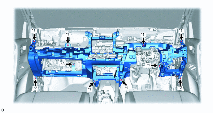
*1 Bolt <E> or <F> *2 Bolt <C> or <D> *3 Bolt <G> - - -
Attach the 2 claws to connect the cooler thermistor.
-
Attach the 2 claws to connect the DLC3.
-
Attach the claw to connect the hood lock control lever.
-
Connect each connector and attach each wire harness clamp.
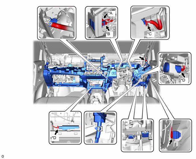
*A for 4WD/AWD *B w/ Power Back Door *C w/ Downhill Assist Control *D w/ Entry and Start System
-
-
INSTALL HEATER TO REGISTER DUCT ASSEMBLY
-
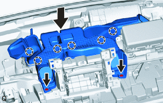
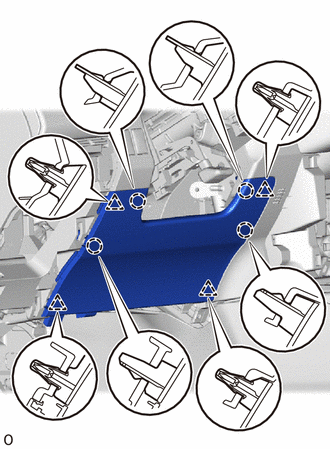
Lower the heater to register duct assembly to attach the 6 claws and install it.
-
Install the 2 clips.
-
-
INSTALL DEFROSTER NOZZLE ASSEMBLY
-
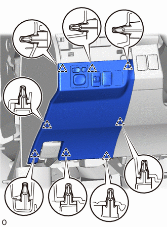
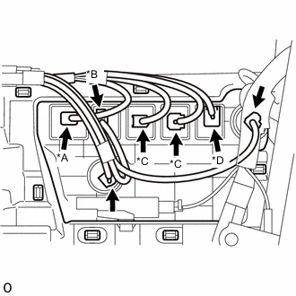
Attach the 3 claws to install the defroster nozzle assembly.
-
Attach the 2 wire harness clamps and connect the connector.
-
-
INSTALL COWL SIDE TRIM BOARD LH
-
Attach the clip to install the cowl side trim board LH.
-
Install the nut.
-
-
INSTALL COWL SIDE TRIM BOARD RH
Tech Tips
Use the same procedure described for the LH side.
-
INSTALL FRONT DOOR SCUFF PLATE LH
-
INSTALL FRONT DOOR SCUFF PLATE RH
-
INSTALL LOWER INSTRUMENT PANEL FINISH PANEL (for LHD without Driver Side Knee Airbag)
-
Attach the 4 clips and 4 claws to install the lower instrument panel finish panel.
-
-
INSTALL LOWER NO. 1 INSTRUMENT PANEL AIRBAG ASSEMBLY (w/ Driver Side Knee Airbag)
-
INSTALL FUSE BOX OPENING COVER
-
for LHD:
-
*A w/ Headlight Leveling *B w/ Light Control Rheostat *C w/ VSC OFF Switch *D w/ Blind Spot Monitor Connect each connector and attach the wire harness clamp.
-
Attach the 8 clips to install the fuse box opening cover.
-
-
for RHD:
-
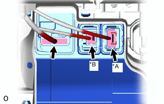
*A w/ VSC OFF Switch *B w/ Headlight Leveling Connect each connector.
-
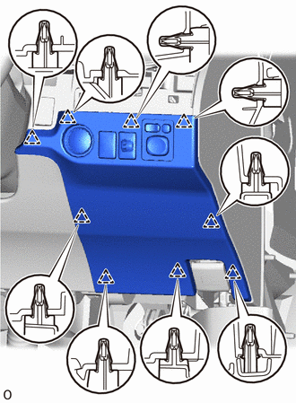
Attach the 9 clips to install the fuse box opening cover.
-
-
-
INSTALL NO. 2 INSTRUMENT PANEL UNDER COVER SUB-ASSEMBLY
-
Attach the 2 guides and 2 claws to install the No. 2 instrument panel under cover sub-assembly.
-
w/ Foot Light:
Connect the connector.
-
-
INSTALL NO. 1 INSTRUMENT PANEL UNDER COVER SUB-ASSEMBLY
-
w/ Tire Pressure Warning System:
Connect the connector.
-
w/ Foot Light:
Connect the connector.
-
Attach the 2 guides and 2 claws to install the No. 1 instrument panel under cover sub-assembly.
-
Install the 2 screws <A> or <B>.
-
-
INSTALL LOWER NO. 2 INSTRUMENT PANEL FINISH PANEL
-
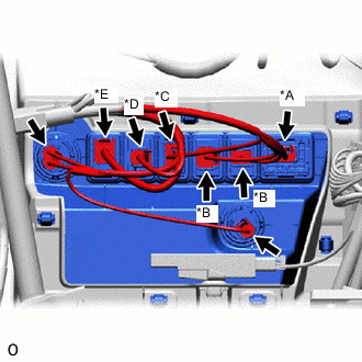
*A w/ Drive Mode Switch *B w/ Seat Heater System *C w/ PTC Heater *D for Windshield Deicer *E w/ USB Audio System for LHD:
Connect each connector.
-
*A w/ Drive Mode Switch *B w/ Lane Departure Alert System *C w/ Seat Heater System *D w/ USB Audio System for RHD:
Connect each connector.
-
Attach the 8 clips to install the lower No. 2 instrument panel finish panel.
-
-
INSTALL REAR CONSOLE BOX SUB-ASSEMBLY
-
INSTALL UPPER INSTRUMENT PANEL
-
CONNECT CABLE TO NEGATIVE BATTERY TERMINAL
Note
When disconnecting the cable, some systems need to be initialized after the cable is reconnected.
-
CHECK SRS WARNING LIGHT
-
w/ Occupant Classification System:
-
w/o Occupant Classification System:
-