LOWER INSTRUMENT PANEL REMOVAL
CAUTION / NOTICE / HINT
Tech Tips
-
Use the same procedure for RHD and LHD vehicles.
-
The procedure listed below is for LHD vehicles.
PROCEDURE
-
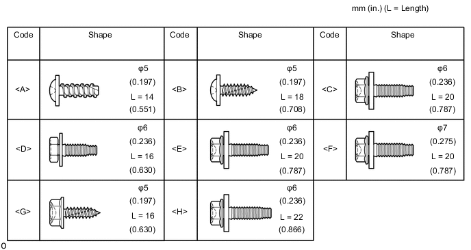
TABLE OF BOLT, SCREW AND NUT
Tech Tips
All bolts, screws and nuts relevant to installing and removing the instrument panel are shown along with their alphabet code in the table below.
-
PRECAUTION
Note
After turning the ignition switch off, waiting time may be required before disconnecting the cable from the battery terminal. Therefore, make sure to read the disconnecting the cable from the battery terminal notice before proceeding with work.
-
DISCONNECT CABLE FROM NEGATIVE BATTERY TERMINAL
CAUTION:
Wait at least 90 seconds after disconnecting the cable from the negative (-) battery terminal to disable the SRS system.
Note
When disconnecting the cable, some systems need to be initialized after the cable is reconnected.
-
REMOVE UPPER INSTRUMENT PANEL
-
REMOVE REAR CONSOLE BOX SUB-ASSEMBLY
-
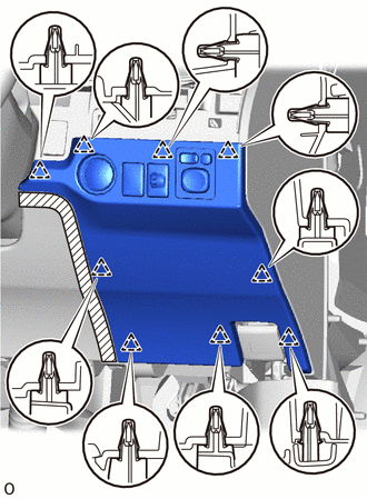
REMOVE LOWER NO. 2 INSTRUMENT PANEL FINISH PANEL
-
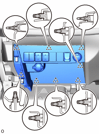
Detach the 8 clips and remove the lower No. 2 instrument panel finish panel.
-
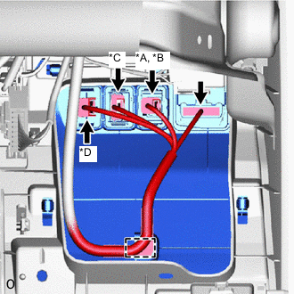
*A w/ Drive Mode Switch *B w/ Seat Heater System *C w/ PTC Heater *D for Windshield Deicer *E w/ USB Audio System for LHD:
Disconnect each connector.
-
*A w/ Drive Mode Switch *B w/ Lane Departure Alert System *C w/ Seat Heater System *D w/ USB Audio System for RHD:
Disconnect each connector.
-
-
REMOVE NO. 1 INSTRUMENT PANEL UNDER COVER SUB-ASSEMBLY
-
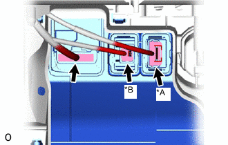
Remove the 2 screws <A> or <B>.
-
Detach the 2 claws and 2 guides and remove the No. 1 instrument panel under cover sub-assembly.
-
w/ Foot Light:
Disconnect the connector.
-
w/ Tire Pressure Warning System:
Disconnect the connector.
-
-
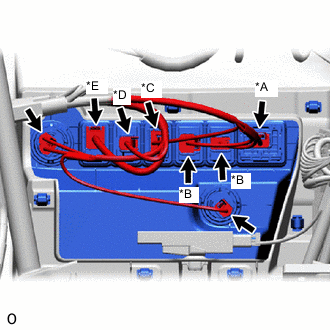
REMOVE FUSE BOX OPENING COVER
-

Protective Tape for LHD:
-
Apply protective tape as shown in the illustration.
-
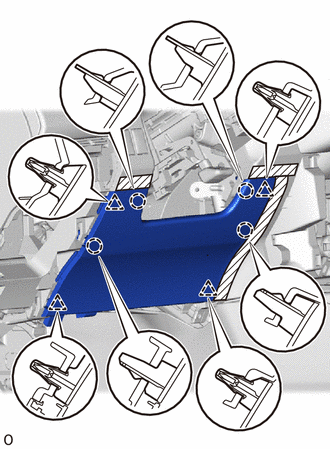
Detach the 8 clips and remove the fuse box opening cover.
-
*A w/ Headlight Leveling *B w/ Light Control Rheostat *C w/ VSC OFF Switch *D w/ Blind Spot Monitor Disconnect each connector and detach the wire harness clamp.
-
-
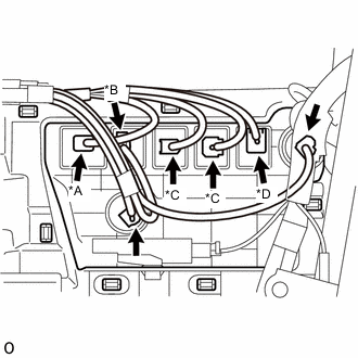
Protective Tape for RHD:
-
Apply protective tape as shown in the illustration.
-
Detach the 9 clips and remove the fuse box opening cover.
-
*A w/ VSC OFF Switch *B w/ Headlight Leveling Disconnect each connector.
-
-
-
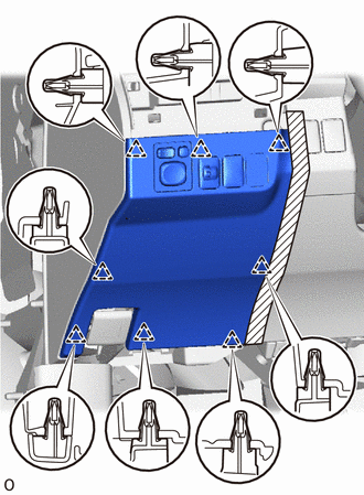
REMOVE LOWER INSTRUMENT PANEL FINISH PANEL (for LHD without Driver Side Knee Airbag)
-
Protective Tape Apply protective tape as shown in the illustration.
-
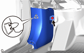
Detach the 4 clips and 4 claws and remove the lower instrument panel finish panel.
-
-
REMOVE LOWER NO. 1 INSTRUMENT PANEL AIRBAG ASSEMBLY (w/ Driver Side Knee Airbag)
-
REMOVE NO. 2 INSTRUMENT PANEL UNDER COVER SUB-ASSEMBLY
-
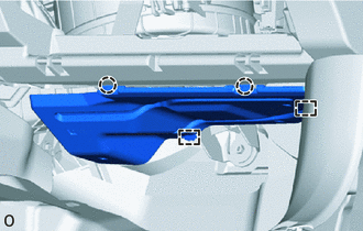
Detach the 2 claws and 2 guides and remove the No. 2 instrument panel under cover sub-assembly.
-
w/ Foot Light:
Disconnect the connector.
-
-
REMOVE FRONT DOOR SCUFF PLATE LH
-
REMOVE FRONT DOOR SCUFF PLATE RH
-
REMOVE COWL SIDE TRIM BOARD LH
-
Remove the nut.
-
Detach the clip and remove the cowl side trim board LH.
-
-
REMOVE COWL SIDE TRIM BOARD RH
Tech Tips
Use the same procedure described for the LH side.
-
REMOVE DEFROSTER NOZZLE ASSEMBLY
-
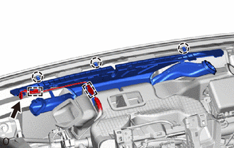
Disconnect the connector and detach the 2 wire harness clamps.
-
Detach the 3 claws and remove the defroster nozzle assembly.
-
-
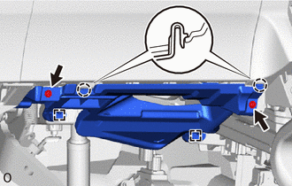
REMOVE HEATER TO REGISTER DUCT ASSEMBLY
-
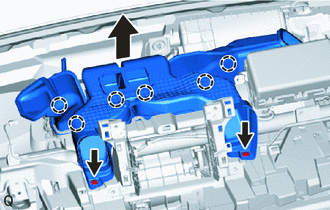
Remove the 2 clips.
-
Pull up the heater to register duct assembly to detach the 6 claws and remove it.
-
-
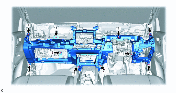
REMOVE LOWER INSTRUMENT PANEL (for LHD)
-
Disconnect each connector and detach each wire harness clamp.
-
Detach the claw and disconnect the hood lock control lever.
-
Detach the 2 claws and disconnect the DLC3.
-
Detach the 2 claws and disconnect the cooler thermistor.

*A for 4WD/AWD *B w/ Power Back Door *C w/ Downhill Assist Control *D w/ Entry and Start System -
Remove the 6 bolts <E> or <F> and 2 bolts <C> or <D>.
-
Remove the bolt <G> and lower instrument panel.
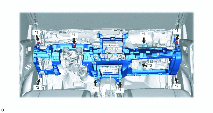
*1 Bolt <E> or <F> *2 Bolt <C> or <D> *3 Bolt <G> - -
-
-
REMOVE LOWER INSTRUMENT PANEL (for RHD)
-
Disconnect each connector and detach each wire harness clamp.
-
Detach the claw and disconnect the hood lock control lever.
-
Detach the 2 claws and disconnect the DLC3.
-
Detach the 2 claws and disconnect the cooler thermistor.
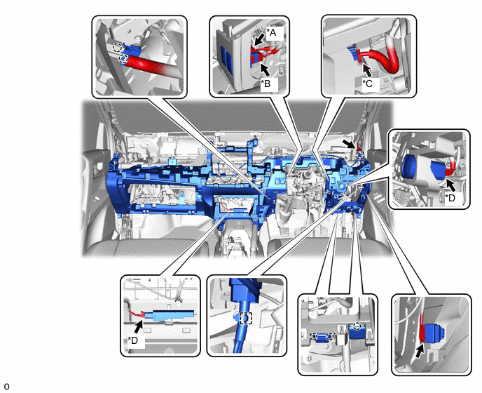
*A for 4WD/AWD *B w/ Power Back Door *C w/ Downhill Assist Control *D w/ Entry and Start System -
Remove the 7 bolts <E> or <F> and 2 bolts <C> or <D>.
-
Remove the bolt <G> and lower instrument panel.
*1 Bolt <E> or <F> *2 Bolt <C> or <D> *3 Bolt <G> - -
-