AIR CONDITIONING PANEL(for Manual Air Conditioning System) INSPECTION
PROCEDURE
-
INSPECT NO. 1 HEATER CONTROL SUB-ASSEMBLY
-
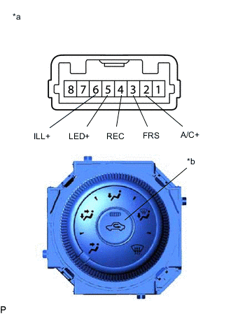
*a Component without harness connected
(No. 1 Heater Control Sub-assembly)
*b Recirculation/fresh Switch Measure the resistance according to the value(s) in the table below.
Standard Resistance Tester Connection Condition Specified Condition 3 (FRS) - 4 (REC) Recirculation/fresh switch: OFF Below 1 Ω 3 (FRS) - 4 (REC) Recirculation/fresh switch: ON 10 kΩ or higher 5 (LED+) - 4 (REC) Recirculation/fresh switch: OFF 10 kΩ or higher 5 (LED+) - 4 (REC) Recirculation/fresh switch: ON Below 30 Ω
-
If the result is not as specified, replace the No. 1 heater control sub-assembly.
-
-
Check that the recirculation/fresh indicator light comes on.
-
Turn the recirculation/fresh switch to ON.
-
Connect a positive (+) lead from the battery to terminal 2 (A/C+) and negative (-) lead to terminal 4 (REC), and check that the recirculation/fresh indicator light comes on.
OK The indicator light comes on.
-
If the result is not as specified, replace the No. 1 heater control sub-assembly.
-
-
-
Check that the illumination light comes on.
-
Connect a positive (+) lead from the battery to terminal 7 (ILL+) and negative (-) lead to terminal 6 (ILL-), and check that the illumination light comes on.
OK The illumination light comes on.
-
If the result is not as specified, replace the No. 1 heater control sub-assembly.
-
-
-
-
INSPECT NO. 2 HEATER CONTROL SUB-ASSEMBLY
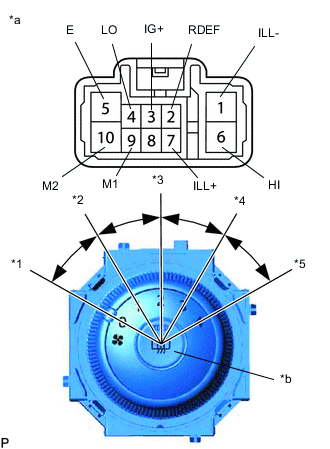
*a Component without harness connected
(No. 2 Heater Control Sub-assembly)
*b Rear Window Defogger Switch *1 Blower Switch OFF Position *2 Blower Switch LO Position *3 Blower Switch M1 Position *4 Blower Switch M2 Position *5 Blower Switch HI Position
-
Model code: ASA44R-ANTXKQ, ASA44R-ANFXKQ, ZSA42R-ANXXKQ, ZSA42R-ANFXKQ, ASA44L-ANTXKV, ASA44L-ANFXKV, ASA42L-ANTXKV, ASA42L-ANFXKV
-
Measure the resistance according to the value(s) in the table below.
Standard Resistance Tester Connection Condition Specified Condition 4 (LO), 6 (HI), 9 (M1), 10 (M2) - 5 (E) Blower switch: 0 10 kΩ or higher 4 (LO) - 5 (E) Blower switch: 1 Below 1 Ω 4 (LO), 9 (M1) - 5 (E) Blower switch: 1 - 2 Below 1 Ω 4 (LO), 9 (M1) - 5 (E) Blower switch: 2 Below 1 Ω 4 (LO), 9 (M1), 10 (M2) - 5 (E) Blower switch: 2 - 3 Below 1 Ω 4 (LO), 10 (M2) - 5 (E) Blower switch: 3 Below 1 Ω 4 (LO), 10 (M2), 6 (HI) - 5 (E) Blower switch: 3 - 4 Below 1 Ω 4 (LO), 6 (HI) - 5 (E) Blower switch: 4 Below 1 Ω 2 (RDEF) - 5 (E) Rear window defogger switch: OFF 10 kΩ or higher 2 (RDEF) - 5 (E) Rear window defogger switch: ON Below 20 Ω If the result is not as specified, replace the No. 2 heater control sub-assembly.
-
Check that the rear window defogger switch indicator light comes on.
-
Connect a positive (+) lead from the battery to terminal 3 (IG+) and negative (-) lead to terminal 5 (E).
-
Push the rear window defogger switch in and check that the indicator light comes on.
OK The indicator light comes on.
If the result is not as specified, replace the No. 2 heater control sub-assembly.
-
-
Check that the illumination light comes on.
-
Connect a positive (+) lead from the battery to terminal 7 (ILL+) and negative (-) lead to terminal 1 (ILL-), and check that the illumination light comes on.
OK The illumination light comes on.
If the result is not as specified, replace the No. 2 heater control sub-assembly.
-
-
-
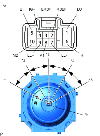
*a Component without harness connected
(No. 2 Heater Control Sub-assembly)
*b Rear Window Defogger Switch *1 Blower Switch OFF Position *2 Blower Switch LO Position *3 Blower Switch M1 Position *4 Blower Switch M1 Position *5 Blower Switch HI Position Model code except: ASA44R-ANTXKQ, ASA44R-ANFXKQ, ZSA42R-ANXXKQ, ZSA42R-ANFXKQ, ASA44L-ANTXKV, ASA44L-ANFXKV, ASA42L-ANTXKV, ASA42L-ANFXKV
-
Measure the resistance according to the value(s) in the table below.
Standard Resistance Tester Connection Condition Specified Condition 1 (LO), 6 (HI), 8 (M1), 10 (M2) - 5 (E) Blower switch: 0 10 kΩ or higher 1 (LO) - 5 (E) Blower switch: 1 Below 1 Ω 1 (LO), 8 (M1) - 5 (E) Blower switch: 1 - 2 Below 1 Ω 1 (LO), 8 (M1) - 5 (E) Blower switch: 2 Below 1 Ω 1 (LO), 8 (M1), 10 (M2) - 5 (E) Blower switch: 2 - 3 Below 1 Ω 1 (LO), 10 (M2) - 5 (E) Blower switch: 3 Below 1 Ω 1 (LO), 10 (M2), 6 (HI) - 5 (E) Blower switch: 3 - 4 Below 1 Ω 1 (LO), 6 (HI) - 5 (E) Blower switch: 4 Below 1 Ω 2 (RDEF) - 3 (ERDF) Rear window defogger switch: OFF 10 kΩ or higher 2 (RDEF) - 3 (ERDF) Rear window defogger switch: ON Below 20 Ω If the result is not as specified, replace the No. 2 heater control sub-assembly.
-
Check that the rear window defogger switch indicator light comes on.
-
Connect a positive (+) lead from the battery to terminal 4 (IG+) and negative (-) lead to terminal 5 (E).
-
Push the rear window defogger switch in and check that the indicator light comes on.
OK The indicator light comes on.
If the result is not as specified, replace the No. 2 heater control sub-assembly.
-
-
Check that the illumination light comes on.
-
Connect a positive (+) lead from the battery to terminal 9 (ILL+) and negative (-) lead to terminal 7 (ILL-), and check that the illumination light comes on.
OK The illumination light comes on.
If the result is not as specified, replace the No. 2 heater control sub-assembly.
-
-
-
-
INSPECT NO. 3 HEATER CONTROL SUB-ASSEMBLY
-
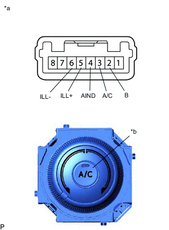
*a Component without harness connected
(No. 3 Heater Control Sub-assembly)
*b A/C Switch Measure the resistance according to the value(s) in the table below.
Standard Resistance Tester Connection Condition Specified Condition 2 (B) - 3 (A/C) A/C switch: ON Below 20 Ω 2 (B) - 3 (A/C) A/C switch: OFF 10 kΩ or higher
-
If the result is not as specified, replace the No. 3 heater control sub-assembly.
-
-
Check that the indicator light comes on.
-
Turn the No. 3 heater control sub-assembly (A/C switch) to the ON position.
-
Connect a positive (+) lead from the battery to terminal 2 (B) and negative (-) lead to terminal 4 (AIND), and check that the indicator light comes on.
OK The indicator light comes on.
-
If the result is not as specified, replace the No. 3 heater control sub-assembly.
-
-
-
Check that the illumination light comes on.
-
Connect a positive (+) lead from the battery to terminal 5 (ILL+) and negative (-) lead to terminal 6 (ILL-), and check that the illumination light comes on.
OK The illumination light comes on.
-
If the result is not as specified, replace the No. 3 heater control sub-assembly.
-
-
-