COMPRESSOR(for 2WW) INSTALLATION
PROCEDURE
-
INSPECT COMPRESSOR OIL
-
When replacing the compressor assembly with pulley with a new one, gradually discharge the refrigerant gas from the service valve, and drain the following amount of oil from the new compressor assembly with pulley before installation.
Standard (Oil capacity inside the new compressor assembly with pulley: 70 to 85 cc (2.37 to 2.87 fl.oz)) - (Remaining oil amount in the removed compressor assembly with pulley) = (Oil amount to be removed from the new compressor) Note
-
If a new compressor assembly with pulley is installed without removing some oil, there will be too much oil in the system due to the oil remaining in the pipes of the vehicle. Excessive oil in the system prevents heat exchange in the refrigeration cycle and causes ineffective cooling.
-
If the amount of oil remaining in the old compressor assembly with pulley is too small, check the air conditioning system for oil leaks.
-
Make sure to use ND-OIL 8 or equivalent compressor oil.
-
-
-
INSTALL COMPRESSOR ASSEMBLY WITH PULLEY
-
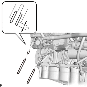
*a Protrusion Height Using a plastic-faced hammer, tap in a new compressor pin.
Standard protrusion height 3.5 to 4.5 mm (0.1378 to 0.1772 in.) -
Using an E8 "TORX" socket wrench, install the 2 stud bolts.
- Torque:
- 9.8 N*m { 100 kgf*cm, 87 in.*lbf }
-
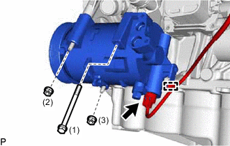
Tighten the 2 nuts and bolt in the order shown in the illustration to install the compressor assembly with pulley.
- Torque:
- 25 N*m { 255 kgf*cm, 18 ft.*lbf }
-
Attach the clamp to connect the wire harness.
-
Connect the connector.
-
-
CONNECT DISCHARGE HOSE SUB-ASSEMBLY
-
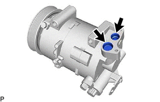
Remove the vinyl tape from the discharge hose sub-assembly and compressor assembly with pulley.
-
Sufficiently apply compressor oil to a new O-ring and the fitting surface of the discharge hose sub-assembly.
Compressor Oil ND-OIL 8 or equivalent -
Install the O-ring to the discharge hose sub-assembly.
Note
Keep the O-rings and O-ring fitting surfaces free of foreign matter.
-
Connect the discharge hose sub-assembly to the compressor assembly with pulley with the bolt.
- Torque:
- 9.8 N*m { 100 kgf*cm, 87 in.*lbf }
-
-
CONNECT SUCTION HOSE SUB-ASSEMBLY
-
Remove the vinyl tape from the suction hose sub-assembly and compressor assembly with pulley.
-
Sufficiently apply compressor oil to a new O-ring and the fitting surface of the suction hose sub-assembly.
Compressor Oil ND-OIL 8 or equivalent -
Install the O-ring to the suction hose sub-assembly.
Note
Keep the O-rings and O-ring fitting surfaces free of foreign matter.
-
Connect the suction hose sub-assembly to the compressor assembly with pulley with the bolt.
- Torque:
- 9.8 N*m { 100 kgf*cm, 87 in.*lbf }
-
-
INSTALL V-RIBBED BELT
-
INSTALL RADIATOR ASSEMBLY
-
CHARGE AIR CONDITIONING SYSTEM WITH REFRIGERANT
-
WARM UP ENGINE
-
INSPECT FOR REFRIGERANT LEAK