AIR CONDITIONING UNIT INSTALLATION
CAUTION / NOTICE / HINT
Tech Tips
-
Use the same procedure for RHD and LHD vehicles.
-
The procedure listed below is for LHD vehicles.
-
A bolt without a torque specification is shown in the standard bolt chart.
PROCEDURE
-
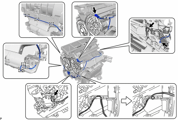
INSTALL AIR CONDITIONING HARNESS ASSEMBLY (for Automatic Air Conditioning System)
-
Route the air conditioning harness assembly as shown in the illustration.
-
Connect each connector.
-
Engage each clamp to install the air conditioning harness assembly.
-
-
INSTALL DRAIN COOLER HOSE
-
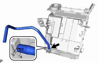
*a Hose Notch *b Rib Align the hose notch and rib as shown in the illustration and install the drain cooler hose.
-
-
INSTALL AIR CONDITIONING AMPLIFIER ASSEMBLY
-
INSTALL CONSOLE MOUNTING BRACKET RH
-
Attach the 2 claws to install the console mounting bracket RH.
-
-
INSTALL CONSOLE MOUNTING BRACKET LH
-
Install the console mounting bracket LH with the screw.
-
-
INSTALL AIR CONDITIONING DUCT SUB-ASSEMBLY (for Automatic Air Conditioning System)
-
Engage the 2 claws to install the air conditioning duct sub-assembly.
-
-
INSTALL BLOWER ASSEMBLY
-
TEMPORARILY INSTALL AIR CONDITIONER UNIT ASSEMBLY
-
Temporarily install the air conditioner unit assembly with the bolt and nut.
Note
To prevent damage to the installation bracket for the air conditioner unit assembly, be sure to support the air conditioner unit assembly in place.
-
Connect the drain cooler hose.
-
-
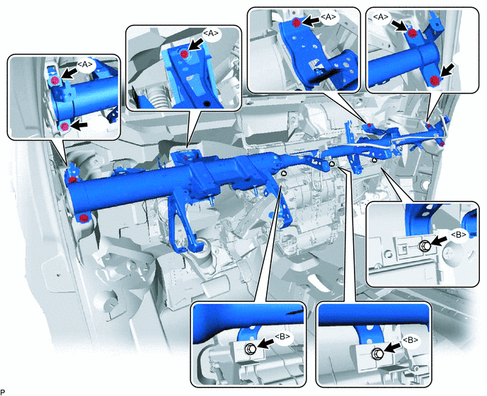
INSTALL INSTRUMENT PANEL REINFORCEMENT ASSEMBLY
-
Install the instrument panel reinforcement assembly with the 6 bolts <A>.
-
Temporarily install the 3 bolts <B>.
-
-
INSTALL NO. 2 INSTRUMENT PANEL BRACE SUB-ASSEMBLY
-
Install the No. 2 instrument panel brace sub-assembly with the bolt, screw and nut.
Tech Tips
Do not fully tighten the screw.
-
Install the front floor carpet assembly to the original position and install the clip.
-
-
INSTALL NO. 1 INSTRUMENT PANEL BRACE SUB-ASSEMBLY
-
Install the No. 1 instrument panel brace sub-assembly with the bolt, screw and nut.
Tech Tips
Do not fully tighten the screw.
-
Install the front floor carpet assembly to the original position and install the clip.
-
-
INSTALL INSTRUMENT PANEL WIRE (for LHD)
-
Attach each clamp.
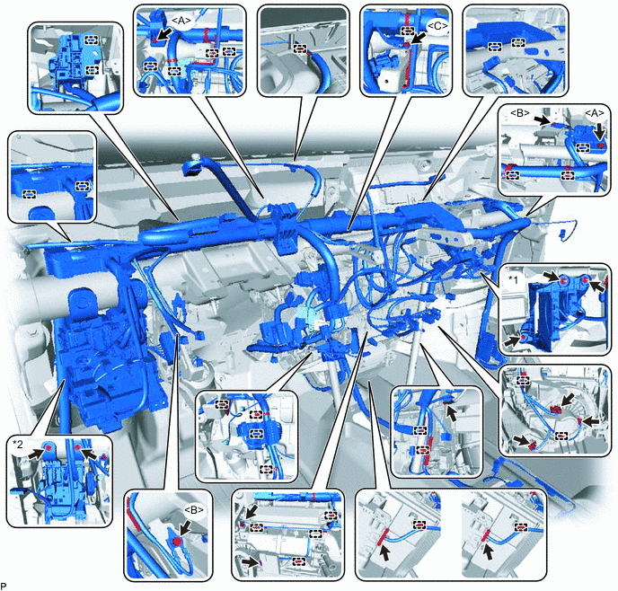
*1 ECU Integration Box RH *2 Instrument Panel Junction Block Assembly -
Connect each connector.
-
Connect the ECU integration box RH with the 2 nuts and bolt.
- Torque:
- for Nut
- 5.5 N*m { 56 kgf*cm, 49 in.*lbf }
- for Bolt
- 12 N*m { 122 kgf*cm, 9 ft.*lbf }
-
Connect the instrument panel junction block assembly with the 2 bolts.
- Torque:
- 3.2 N*m { 33 kgf*cm, 28 in.*lbf }
-
Connect the instrument panel wire with the 2 bolts <A>.
- Torque:
- 8.4 N*m { 86 kgf*cm, 74 in.*lbf }
-
Connect the ground wire with the 3 bolts.
- Torque:
- for Bolt <B>
- 8.4 N*m { 86 kgf*cm, 74 in.*lbf }
- for Bolt <C>
- 8.5 N*m { 87 kgf*cm, 75 in.*lbf }
-
w/ PTC Heater:
Connect the 2 or 3 connectors.
-
-
INSTALL INSTRUMENT PANEL WIRE (for RHD)
-
Attach each clamp.
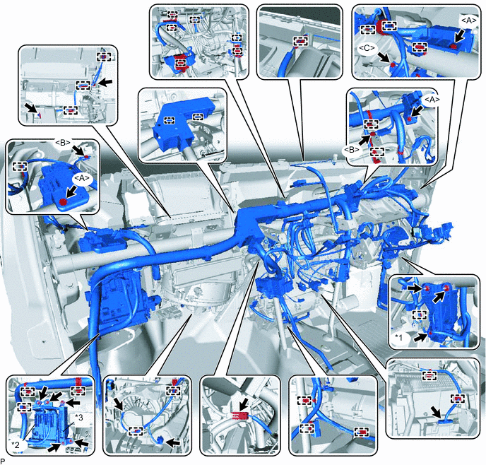
*1 ECU Integration Box RH *2 Instrument Panel Junction Block Assembly *3 Engeine Stop and Start ECU - - -
Connect each connector.
-
Connect the ECU integration box RH with the 3 bolts.
- Torque:
- for Nut
- 5.5 N*m { 56 kgf*cm, 49 in.*lbf }
- for Bolt
- 12 N*m { 122 kgf*cm, 9 ft.*lbf }
-
Connect the instrument panel junction block assembly with the 2 nuts and bolt.
- Torque:
- for Nut
- 8.4 N*m { 86 kgf*cm, 74 in.*lbf }
- for Bolt
- 8.4 N*m { 86 kgf*cm, 74 in.*lbf }
-
Install the engine stop and start ECU with the bolt and nut.
- Torque:
- 8.0 N*m { 82 kgf*cm, 71 in.*lbf }
-
Connect the instrument panel wire with the 3 bolts <A>.
- Torque:
- 8.4 N*m { 86 kgf*cm, 74 in.*lbf }
-
Connect the ground wire with the 3 bolts.
- Torque:
- for Bolt <B>
- 8.4 N*m { 86 kgf*cm, 74 in.*lbf }
- for Bolt <C>
- 8.5 N*m { 87 kgf*cm, 75 in.*lbf }
-
w/ PTC Heater:
Connect the 2 or 3 connectors.
-
-
INSTALL AIR CONDITIONER UNIT ASSEMBLY
-
for LHD:
Tighten the 4 bolts, 2 screws and nut.
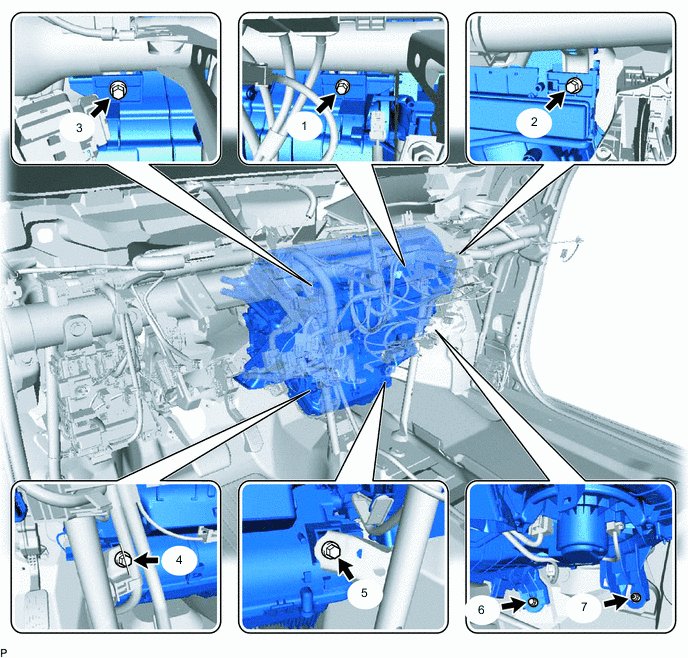
- Torque:
- for Bolt
- 9.8 N*m { 100 kgf*cm, 7 ft.*lbf }
Note
Tighten the bolts, screws and nut in the order shown in the illustration to install the air conditioner unit assembly.
-
for RHD:
Tighten the 4 bolts, 2 screws and nut.
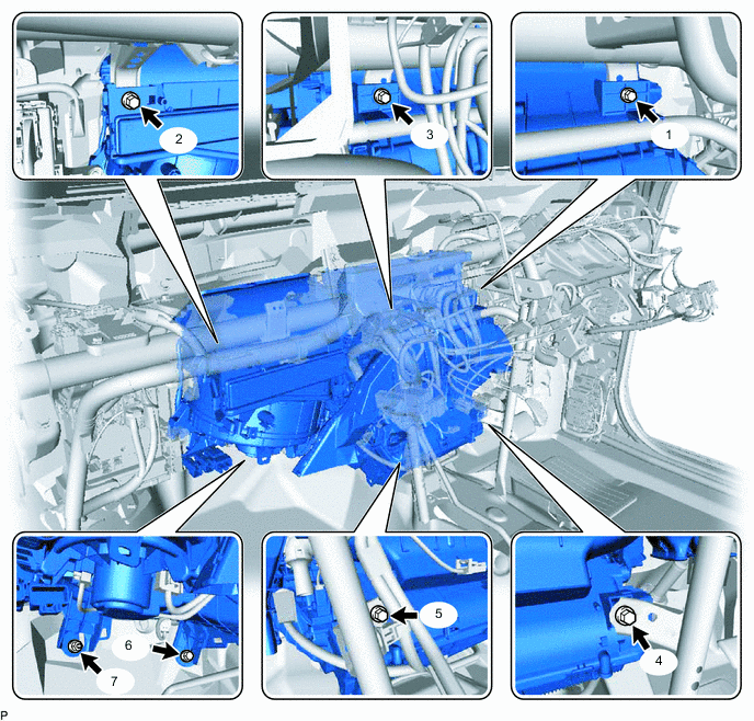
- Torque:
- for Bolt
- 9.8 N*m { 100 kgf*cm, 7 ft.*lbf }
Note
Tighten the bolts, screws and nut in the order shown in the illustration to install the air conditioner unit assembly.
-
-
INSTALL NO. 3 AIR DUCT SUB-ASSEMBLY
-
Attach the 2 claws to install the No. 3 air duct sub-assembly.
Note
If any of the claws of the No. 3 air duct sub-assembly are cracked or deformed, make sure to replace the air duct with a new one. Failure to do so may cause the No. 3 air duct sub-assembly to fall off or noise to occur.
-
-
INSTALL NO. 2 AIR DUCT SUB-ASSEMBLY
-
Attach the 2 claws to install the No. 2 air duct sub-assembly.
Note
If any of the claws of the No. 2 air duct sub-assembly are cracked or deformed, make sure to replace the air duct with a new one. Failure to do so may cause the No. 2 air duct sub-assembly to fall off or noise to occur.
-
-
INSTALL DEFROSTER NOZZLE ASSEMBLY
-
Attach the 3 hooks to install the defroster nozzle assembly.
-
Connect the automatic light control sensor (solar sensor) connector and attach the 2 harness clamps.
-
-
INSTALL AIR DUCT ASSEMBLY
-
Install the air duct assembly with the 2 nuts.
- Torque:
- 9.8 N*m { 100 kgf*cm, 87 in.*lbf }
-
-
INSTALL REAR NO. 1 AIR DUCT
-
Attach the 8 claws to install the rear No. 1 air duct.
-
-
INSTALL STEERING COLUMN ASSEMBLY
-
INSTALL LOWER INSTRUMENT PANEL SUB-ASSEMBLY
-
CONNECT HEATER WATER HOSE
-
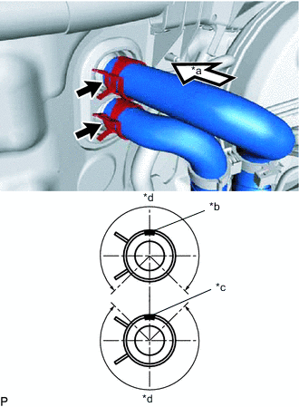
*a View A *b Heater Water Outlet Hose Paint Mark *c Heater Water Inlet Hose Paint Mark *d Clip installation angle (270°) Connect the heater water outlet hose A and heater water inlet hose A with the paint mark facing up and attach the clip within the area shown in the illustration.
Paint Mark Color Engine Transmission Hose Color 2AR All Outlet Purple Inlet Purple 3ZR Manual Transmission Outlet Pink Inlet Pink CVT Outlet Pink Inlet Orange 1AD, 2AD w/o Fuel Heater Outlet Blue Inlet Blue w/ Fuel Heater Outlet Grean Inlet Grean Note
Do not apply excessive force to the heater water outlet hose A and heater water inlet hose A.
-
-
CONNECT AIR CONDITIONING TUBE
-
Remove the vinyl tape from the suction tube sub-assembly and liquid tube sub-assembly.
-
Sufficiently apply compressor oil to 2 new O-rings and fitting surface of the suction tube sub-assembly and liquid tube sub-assembly.
Compressor Oil ND-OIL 8 or equivalent -
Install the 2 O-rings to the suction tube sub-assembly liquid tube sub-assembly.
-
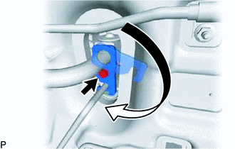
Connect the liquid tube sub-assembly and suction tube sub-assembly.
-
Rotate the hook connector in the direction indicated by the arrow in the illustration and install the bolt.
- Torque:
- 9.8 N*m { 100 kgf*cm, 87 in.*lbf }
-
-
CONNECT CABLE TO NEGATIVE BATTERY TERMINAL
Note
When disconnecting the cable, some systems need to be initialized after the cable is reconnected.
-
ADD ENGINE COOLANT
for 1AD-FTV: Click here
for 2AD-FHV: Click here
for 2AD-FTV: Click here
for 2AR-FE: Click here
for 3ZR-FAE: Click here
for 3ZR-FE: Click here
-
CHARGE AIR CONDITIONING SYSTEM WITH REFRIGERANT
-
WARM UP ENGINE
-
INSPECT FOR COOLANT LEAK
for 1AD-FTV: Click here
for 2AD-FHV: Click here
for 2AD-FTV: Click here
for 2AR-FE: Click here
for 3ZR-FAE: Click here
for 3ZR-FE: Click here
-
INSPECT FOR REFRIGERANT LEAK
-
INITIALIZATION SERVO MOTOR
for Automatic Air Conditioning system: Click here