AIR CONDITIONING UNIT REMOVAL
CAUTION / NOTICE / HINT
Tech Tips
-
Use the same procedure for RHD and LHD vehicles.
-
The procedure listed below is for LHD vehicles.
PROCEDURE
-
DRAIN ENGINE COOLANT
for 2AD-FHV: Click here
for 2AD-FTV: Click here
for 2AR-FE: Click here
for 3ZR-FAE: Click here
for 3ZR-FE: Click here
for 2WW: Click here
-
REMOVE NO. 1 ENGINE COVER (for 2WW)
-
REMOVE NO. 3 COWL TOP PANEL INSULATOR (for 2WW)
-
RECOVER REFRIGERANT FROM REFRIGERATION SYSTEM
-
for HFC-134a (R134a):
-
for HFO-1234yf (R1234yf):
-
-
PRECAUTION
Note
-
After turning the ignition switch off, waiting time may be required before disconnecting the cable from the battery terminal. Therefore, make sure to read the disconnecting the cable from the battery terminal notice before proceeding with work.
-
for Automatic Air Conditioning System:
Make sure to select FACE mode before disconnecting the cable from the negative (-) battery terminal.
-
-
DISCONNECT CABLE FROM NEGATIVE BATTERY TERMINAL
CAUTION:
Wait at least 90 seconds after disconnecting the cable from the negative (-) battery terminal to disable the SRS system.
Note
When disconnecting the cable, some systems need to be initialized after the cable is reconnected.
-
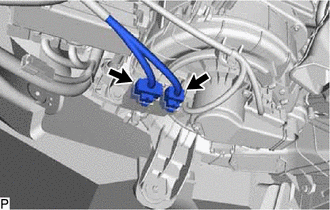
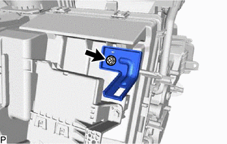
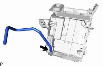
DISCONNECT AIR CONDITIONING TUBE (except Sub-cool Accelerator)
-
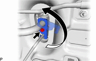
Remove the bolt and rotate the hook connector.
-
Disconnect the suction tube sub-assembly.
-
Remove the O-ring from the suction tube sub-assembly.
Note
Seal the openings of the disconnected parts using vinyl tape to prevent the entry of moisture and foreign matter.
-
Disconnect the liquid tube sub-assembly.
-
Remove the O-ring from the liquid tube sub-assembly.
Note
Seal the openings of the disconnected parts using vinyl tape to prevent the entry of moisture and foreign matter.
-
-
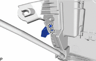
DISCONNECT SUCTION PIPE SUB-ASSEMBLY (for Sub-cool Accelerator)
-
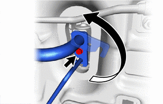
Remove the bolt and rotate the hook connector.
-
Disconnect the suction pipe sub-assembly.
-
Remove the 2 O-rings from the suction pipe sub-assembly.
Note
Seal the openings of the disconnected parts using vinyl tape to prevent the entry of moisture and foreign matter.
-
-
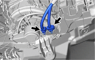
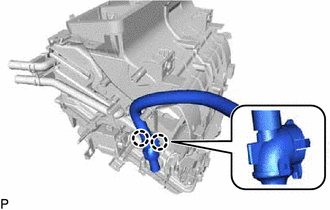
DISCONNECT HEATER WATER HOSE
-
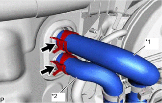
*1 Heater Water Outlet Hose A *2 Heater Water Inlet Hose A Using pliers, grip the claws of the clip and slide the clip to disconnect the heater water outlet hose A.
-
Using pliers, grip the claws of the clip and slide the clip to disconnect the heater water inlet hose A.
Note
-
Do not apply excessive force to the heater water outlet hose A and heater water inlet hose A.
-
Prepare a drain pan or cloth in case the coolant leaks.
-
-
-
REMOVE LOWER INSTRUMENT PANEL SUB-ASSEMBLY
-
REMOVE STEERING COLUMN ASSEMBLY
-
REMOVE REAR NO. 1 AIR DUCT
-
Detach the 8 claws and remove the rear No. 1 air duct.
-
-
REMOVE AIR DUCT ASSEMBLY
-
Remove the 2 nuts and air duct assembly.
-
-
REMOVE DEFROSTER NOZZLE ASSEMBLY
-
Disconnect the automatic light control sensor (solar sensor) connector and detach the 2 harness clamps.
-
Detach the 3 hooks and remove the defroster nozzle assembly.
-
-
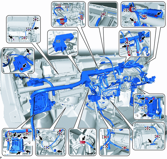
DISCONNECT INSTRUMENT PANEL WIRE (for LHD)
-
w/ PTC Heater:
Disconnect the connectors.
-
Remove the 2 bolts and disconnect the instrument panel junction block assembly.
*1 Instrument Panel Junction Block Assembly *2 ECU Integration Box RH -
Remove the bolt and 2 nuts and disconnect the ECU integration box RH.
-
Disconnect each connector.
-
Remove the 3 bolts and disconnect each ground wire.
-
Detach each clamp and remove the 2 bolts to disconnect the instrument panel wire.
-
-
DISCONNECT INSTRUMENT PANEL WIRE (for RHD)
-
w/ PTC Heater:
Disconnect the connectors.
-
Remove the bolt and nut and disconnect the engine start and stop ECU.
*1 Eengine Stop and Start ECU *2 Instrument Panel Junction Block Assembly *3 ECU Integration Box RH - - -
Remove the 2 nuts and bolt and disconnect the instrument panel junction block assembly.
-
Remove the bolt and 2 nuts and disconnect the ECU integration box RH.
-
Disconnect each connector.
-
Remove the 3 bolts and disconnect each ground wire.
-
Detach each clamp and remove the 3 bolts to disconnect the instrument panel wire.
-
-
REMOVE NO. 1 INSTRUMENT PANEL BRACE SUB-ASSEMBLY
-
Using a clip remover, remove the clip and then fold back the front floor carpet assembly.
-
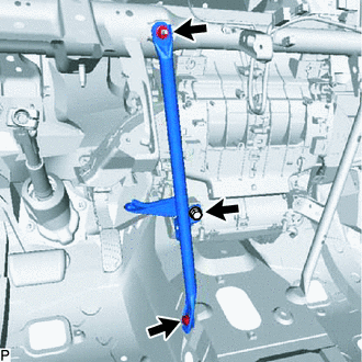
Remove the bolt, screw, nut and No. 1 instrument panel brace sub-assembly.
-
-
REMOVE NO. 2 INSTRUMENT PANEL BRACE SUB-ASSEMBLY
-
Using a clip remover, remove the clip and then fold back the front floor carpet assembly.
-
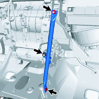
Remove the bolt, screw, nut and No. 2 instrument panel brace sub-assembly.
-
-
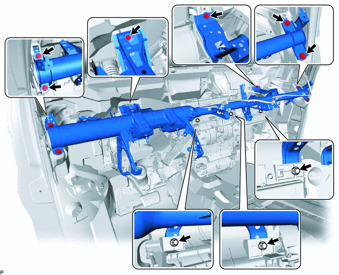
REMOVE INSTRUMENT PANEL REINFORCEMENT ASSEMBLY
-
Remove the 9 bolts and instrument panel reinforcement assembly.
-
-
REMOVE NO. 2 AIR DUCT SUB-ASSEMBLY
-
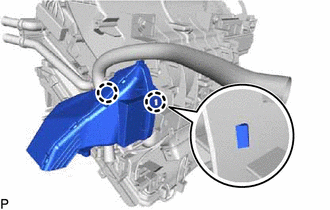
Detach the 2 claws and remove the No. 2 air duct sub-assembly.
Note
If any of the claws of the No. 2 air duct sub-assembly have been cracked or deformed during removal, make sure to replace the air duct with a new one. Failure to do so may cause the No. 2 air duct sub-assembly to fall off or noise to occur.
-
-
REMOVE NO. 3 AIR DUCT SUB-ASSEMBLY
-
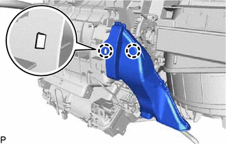
Detach the 2 claws and remove the No. 3 air duct sub-assembly.
Note
If any of the claws of the No. 3 air duct sub-assembly have been cracked or deformed during removal, make sure to replace the air duct with a new one. Failure to do so may cause the No. 3 air duct sub-assembly to fall off or noise to occur.
-
-
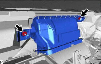
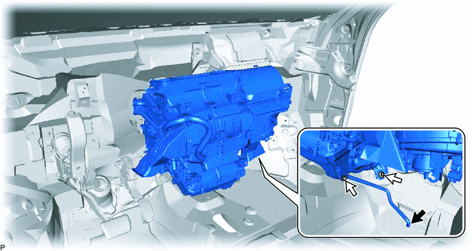
REMOVE AIR CONDITIONER UNIT ASSEMBLY
-
Disconnect the drain cooler hose.
-
Remove the bolt, nut and air conditioner unit assembly.
-
-
REMOVE BLOWER ASSEMBLY
-
REMOVE SKID CONTROL BUZZER ASSEMBLY (for RHD)
-
REMOVE AIR CONDITIONING DUCT SUB-ASSEMBLY (for Automatic Air Conditioning System)
-
Disengage the 2 claws and remove the air conditioning duct sub-assembly.
-
-
REMOVE CONSOLE MOUNTING BRACKET LH
-
Remove the screw and console mounting bracket LH.
-
-
REMOVE CONSOLE MOUNTING BRACKET RH
-
Disengage the 2 claws to remove the console mounting bracket RH.
-
-
REMOVE AIR CONDITIONING AMPLIFIER ASSEMBLY
-
REMOVE DRAIN COOLER HOSE
-
Remove the drain cooler hose.
-
-
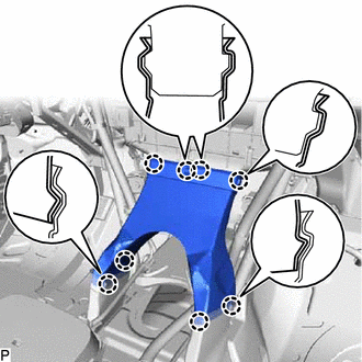
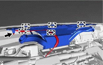
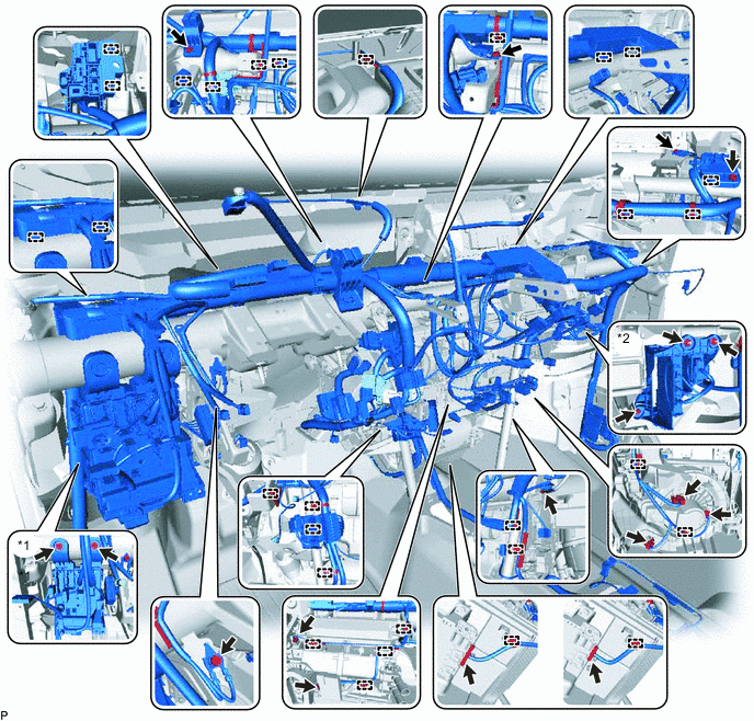
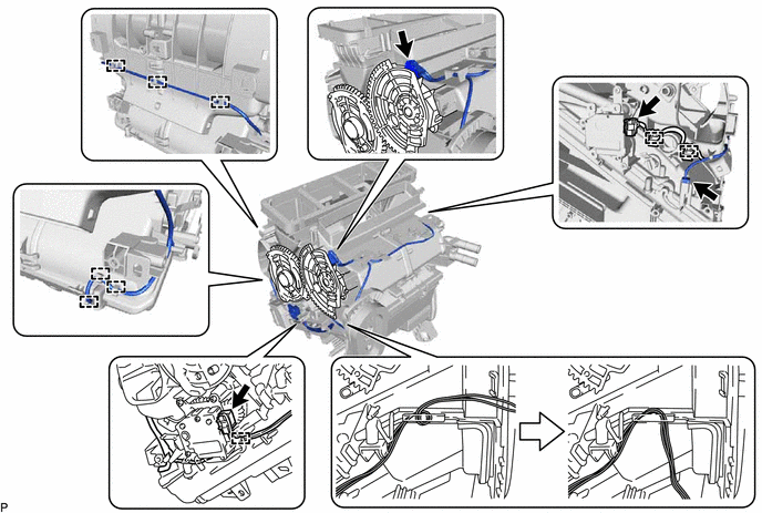
REMOVE AIR CONDITIONING HARNESS ASSEMBLY (for Automatic Air Conditioning System)
-
Detach each clamp.
-
Disconnect each connector.
-
Remove the air conditioning harness assembly as shown in the illustration.
-