BLOWER UNIT REASSEMBLY
CAUTION / NOTICE / HINT
Tech Tips
-
Use the same procedure for RHD and LHD vehicles.
-
The procedure listed below is for LHD vehicles.
-
A bolt without a torque specification is shown in the standard bolt chart.
PROCEDURE
-
INSTALL NO. 1 BLOWER DAMPER SERVO SUB-ASSEMBLY (for Manual Air Conditioning System)
-
Install the link of the No. 1 blower damper servo sub-assembly to the link of the blower assembly as shown in the illustration.
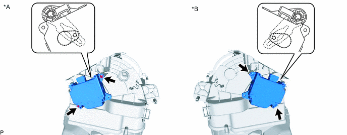
*A for LHD *B for RHD -
Install the No. 1 blower damper servo sub-assembly with the 2 screws.
-
-
INSTALL NO. 1 BLOWER DAMPER SERVO SUB-ASSEMBLY (for Automatic Air Conditioning System)
-
Install the link of the No. 1 blower damper servo sub-assembly to the link of the blower assembly as shown in the illustration.
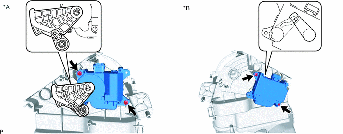
*A for LHD *B for RHD -
Install the No. 1 blower damper servo sub-assembly with the 2 screws.
-
-
INSTALL BLOWER MOTOR WITH FAN SUB-ASSEMBLY (for Manual Air Conditioning System)
-
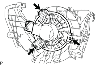
Install the blower motor with fan sub-assembly with the 3 screws.
-
-
INSTALL BLOWER MOTOR WITH FAN SUB-ASSEMBLY (for Automatic Air Conditioning System)
-
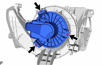
Install the blower motor with fan sub-assembly with the 3 screws.
-
-
INSTALL BLOWER RESISTOR (for Manual Air Conditioning System)
-
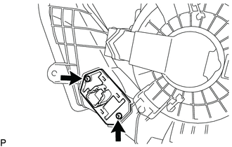
Install the blower resistor with the 2 screws.
-