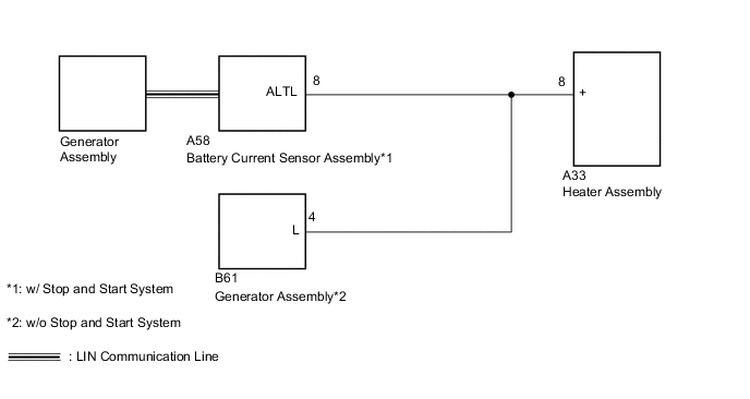
COMBUSTION TYPE POWER HEATER SYSTEM Power Heater Alternator Circuit
DESCRIPTION
The heater assembly receives engine operation signals from the battery current sensor assembly*1 or generator assembly*2. If this circuit is open, the heater assembly will determine that the engine operation signals indicate on. If this circuit is shorted, the heater assembly will determine that the engine operation signals indicate off and the heater assembly will not operate.
-
*1: w/ Stop and Start System
*2: w/o Stop and Start System
WIRING DIAGRAM
CAUTION / NOTICE / HINT
Note
First, confirm that there are no malfunctions in the LIN communication systems. Refer to the how to proceed with troubleshooting procedure.
PROCEDURE
-
INSPECT GENERATOR ASSEMBLY
-
Remove the generator assembly.
for 1AD-FTV:
for 2AD-FHV:
for 2AD-CCo, 2AD-DPF:
-
Inspect the generator assembly.
for 1AD-FTV:
for 2AD-FHV:
for 2AD-CCo, 2AD-DPF:
Result Proceed to OK (w/ Stop and Start System) OK (w/o Stop and Start System) NG
OK (w/o Stop and Start System) 
CHECK HARNESS AND CONNECTOR (HEATER ASSEMBLY - GENERATOR ASSEMBLY) Click here
NG 
REPLACE GENERATOR ASSEMBLY for 1AD-FTV: REPLACE GENERATOR ASSEMBLY Click here
REPLACE GENERATOR ASSEMBLY for 2AD-FHV: REPLACE GENERATOR ASSEMBLY Click here
REPLACE GENERATOR ASSEMBLY for 2AD-CCo, 2AD-DPF: REPLACE GENERATOR ASSEMBLY Click hereOK (w/ Stop and Start System) 
-
-
CHECK HARNESS AND CONNECTOR (HEATER ASSEMBLY - GENERATOR CONTROL ECU ASSEMBLY)
-
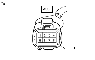
*a Front view of wire harness connector
(to Heater Assembly)
Disconnect the heater assembly connector.
-
Measure the voltage according to the value(s) in the table below.
Standard Voltage Tester Connection Condition Specified Condition A33-8 (+) - Body ground Engine is running (Generator assembly operate) 11 to 14 V Result Proceed to OK NG
OK
PROCEED TO NEXT SUSPECTED AREA SHOWN IN PROBLEM SYMPTOMS TABLE Click here
NG
CHECK HARNESS AND CONNECTOR (HEATER ASSEMBLY - BATTERY CURRENT SENSOR ASSEMBLY) Click here
-
-
CHECK HARNESS AND CONNECTOR (HEATER ASSEMBLY - GENERATOR ASSEMBLY)
-
*a Front view of wire harness connector
(to Heater Assembly)
Disconnect the heater assembly connector.
-
Measure the voltage according to the value(s) in the table below.
Standard Voltage Tester Connection Condition Specified Condition A33-8 (+) - Body ground Engine is running (Generator assembly operate) 11 to 14 V Result Proceed to OK NG
OK
PROCEED TO NEXT SUSPECTED AREA SHOWN IN PROBLEM SYMPTOMS TABLE Click here
NG
CHECK HARNESS AND CONNECTOR (HEATER ASSEMBLY - GENERATOR ASSEMBLY) Click here
-
-
CHECK HARNESS AND CONNECTOR (HEATER ASSEMBLY - BATTERY CURRENT SENSOR ASSEMBLY)
-
Disconnect the A33 heater assembly connector.
-
Disconnect the A58 battery current sensor assembly connector.
-
Measure the resistance according to the value(s) in the table below.
Standard Resistance Tester Connection Condition Specified Condition A33-8 (+) - A58-8 (ALTL) Always Below 1 Ω A33-8 (+) - Body ground Always 10 kΩ or higher Result Proceed to OK NG
OK
REPLACE BATTERY CURRENT SENSOR ASSEMBLY for 1AD-FTV: REPLACE BATTERY CURRENT SENSOR ASSEMBLY Click here
REPLACE BATTERY CURRENT SENSOR ASSEMBLY for 2AD-FHV: REPLACE BATTERY CURRENT SENSOR ASSEMBLY Click here
REPLACE BATTERY CURRENT SENSOR ASSEMBLY for 2AD-CCo, 2AD-DPF: REPLACE BATTERY CURRENT SENSOR ASSEMBLY Click hereNG
REPAIR OR REPLACE HARNESS OR CONNECTOR
-
-
CHECK HARNESS AND CONNECTOR (HEATER ASSEMBLY - GENERATOR ASSEMBLY)
-
Disconnect the A33 heater assembly connector.
-
Disconnect the B61 generator assembly connector.
-
Measure the resistance according to the value(s) in the table below.
Standard Resistance Tester Connection Condition Specified Condition A33-8 (+) - B61-4 (L) Always Below 1 Ω A33-8 (+) - Body ground Always 10 kΩ or higher Result Proceed to OK NG
OK
REPLACE GENERATOR ASSEMBLY for 1AD-FTV: REPLACE GENERATOR ASSEMBLY Click here
REPLACE GENERATOR ASSEMBLY for 2AD-FHV: REPLACE GENERATOR ASSEMBLY Click here
REPLACE GENERATOR ASSEMBLY for 2AD-CCo, 2AD-DPF: REPLACE GENERATOR ASSEMBLY Click hereNG
REPAIR OR REPLACE HARNESS OR CONNECTOR
-