COMBUSTION TYPE POWER HEATER SYSTEM, Diagnostic DTC:054, 056
| DTC Code | DTC Name |
|---|---|
| 054 | High Setting of Flame Cutout |
| 056 | Low Setting of Flame Cutout |
DESCRIPTION
| DTC No. | Detection Item | DTC Detection Condition | Trouble Area |
|---|---|---|---|
| 054 | High Setting of Flame Cutout | Combustion ends abnormally (High output operation). |
|
| 056 | Low Setting of Flame Cutout | Combustion ends abnormally (Low output operation). |
|
CAUTION / NOTICE / HINT
Tech Tips
Before performing the following procedure, attempt to restart the heater assembly. If the heater assembly is successfully started, confirm that neither DTC 054 nor DTC 056 is output. If neither DTC 054 nor 056 is output, finish troubleshooting because it can be concluded that the system has returned to normal operation.
PROCEDURE
-
INSPECT INTAKE AIR DUCT
-
Inspect the intake air duct.
Result Result Proceed to There is no problem with the intake air duct A The intake air duct is clogged, or other problems are found B
B 
CLEAN OR REPLACE INTAKE AIR DUCT
A 
-
-
INSPECT EXHAUST AIR DUCT
-
Inspect the exhaust air duct.
Result Result Proceed to There is no problem with the exhaust air duct A The exhaust air duct is clogged, or other problems are found B
B
CLEAN OR REPLACE EXHAUST AIR DUCT
A
-
-
INSPECT HEATER PUMP ASSEMBLY
-
Remove the heater pump assembly connector.
-
Measure the resistance according to the value(s) in the table below.
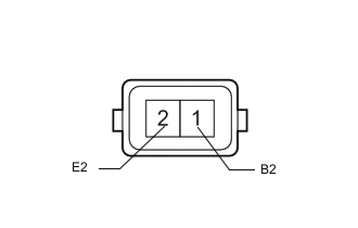
Standard Resistance Tester Connection Condition Specified Condition 1 (B2) - 2 (E2) Always 9 to 12 Ω -
Inspect heater pump assembly operation.
-
Connect a positive (+) lead from the battery to terminal 1 (B2) and a negative (-) lead to terminal 2 (E2), and check the pressure of the hose by hand.
Note
This inspection must be done quickly (within 10 seconds) to prevent damage to the heater pump assembly.
OK The pressure is applied to the hose.
Result Proceed to OK NG -
NG
REPLACE HEATER PUMP ASSEMBLY Click here
OK
-
-
CHECK FUEL PUMP FILTER
-
Replace the fuel filter with a new one and check that the condition returns to normal.
OK The heater is ignited normally and starts operating. Result Proceed to OK NG
OK
END (FUEL PUMP FILTER IS DEFECTIVE)
NG
REPLACE HEATER ASSEMBLY Click here
-