COMBUSTION TYPE POWER HEATER SYSTEM Power Heater Fuel Pump Circuit
DESCRIPTION
When the heater switch assembly is turned on, the heater pump assembly receives a drive voltage from the heater assembly. The heater pump assembly provides the heater assembly with fuel necessary for combustion, allowing the heater assembly to operate.
WIRING DIAGRAM
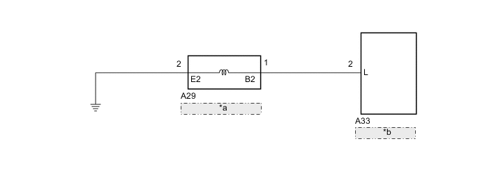
| *a | Heater Pump Assembly |
| *b | Heater Assembly |
PROCEDURE
-
CHECK HARNESS AND CONNECTOR (HEATER ASSEMBLY - HEATER PUMP ASSEMBLY)
-
Disconnect the A33 heater assembly connector.
-
Disconnect the A29 heater pump assembly connector.
-
Measure the resistance according to the value(s) in the table below.
Standard Resistance Tester Connection Condition Specified Condition A33-2 (L) - A29-1 (B2) Always Below 1 Ω A33-2 (L) - Body ground Always 10 kΩ or higher Result Proceed to OK NG
NG 
REPAIR OR REPLACE HARNESS OR CONNECTOR
OK 
-
-
CHECK HARNESS AND CONNECTOR (HEATER PUMP ASSEMBLY - BODY GROUND)
-
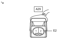
*a Front view of wire harness connector
(to Heater Pump Assembly)
Disconnect the heater pump assembly connector.
-
Measure the resistance according to the value(s) in the table below.
Standard Resistance Tester Connection Condition Specified Condition A29-2 (E2) - Body ground Always Below 1 Ω Result Proceed to OK NG
NG
REPAIR OR REPLACE HARNESS OR CONNECTOR
OK
-
-
INSPECT HEATER PUMP ASSEMBLY
-
Remove the heater pump assembly.
-
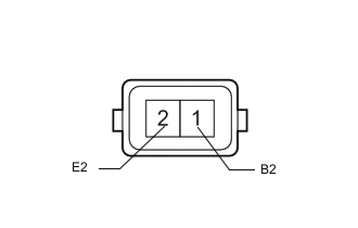
Measure the resistance according to the value(s) in the table below.
Standard Resistance Tester Connection Condition Specified Condition 1 (B2) - 2 (E2) Always 9 to 12 Ω -
Inspect heater pump assembly operation.
-
Connect a positive (+) lead from the battery to terminal 1 (B2) and a negative (-) lead to terminal 2 (E2), and check the pressure of the hose by hand.
Note
This inspection must be done quickly (within 10 seconds) to prevent damage to the heater pump assembly.
OK The pressure is applied to the hose.
Result Proceed to OK NG -
NG
REPLACE HEATER PUMP ASSEMBLY Click here
OK
-
-
CHECK HEATER ASSEMBLY
-
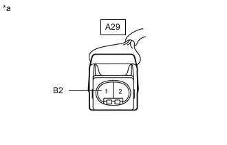
*a Front view of wire harness connector
(to Heater Pump Assembly)
Disconnect the heater pump assembly connector.
-
Measure the voltage according to the value(s) in the table below.
Standard Voltage Tester Connection Condition Specified Condition A29-1 (B2) - Body ground Engine running
Heater switch assembly on
11 to 14 V A29-1 (B2) - Body ground Engine running
Heater switch assembly off
Below 1 V Result Proceed to OK NG
OK
PROCEED TO NEXT SUSPECTED AREA SHOWN IN PROBLEM SYMPTOMS TABLE Click here
NG
REPLACE HEATER ASSEMBLY Click here
-