COMBUSTION TYPE POWER HEATER SYSTEM TERMINALS OF ECU
-
INSPECT HEATER ASSEMBLY

-
Measure the voltage, resistance and waveform according to the value(s) in the table below.
Terminal No. (Symbol) Wiring Color Terminal Description Condition Specified Condition A33-1 (E) - Body ground W-B - Body ground Ground for main power supply Always Below 1 Ω A33-2 (L) - Body ground G - Body ground Fuel pump operation signal Engine running
Heater switch assembly on
Pulse generation
(See waveform 1)
A33-3 (IG) - Body ground LG - Body ground Power heater operating signal Ignition switch ON
Heater switch assembly on
11 to 14 V A33-3 (IG) - Body ground LG - Body ground Power heater operating signal Ignition switch off
Heater switch assembly off
Below 1 V A33-5 (B) - Body ground R - Body ground Power source Always 11 to 14 V A33-8 (+) - Body ground W - Body ground*1
V - Body ground*2
Engine operating signal Engine running
(Generator assembly operating)
11 to 14 V *1: w/ Stop and Start System
*2: w/o Stop and Start System
-
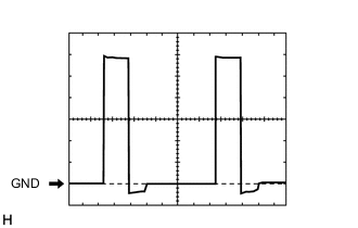
Waveform 1:
Heater Fuel Pump Control Signal Item Content Terminal No. (Symbol) A33-2 (L) - Body ground Tool Setting 2 V/DIV., 20 ms/DIV. Vehicle Condition Engine running
Heater switch assembly on
-