AIR CONDITIONING SYSTEM(for Manual Air Conditioning System) ECO Switch Circuit
DESCRIPTION
When the combination switch assembly (ECO mode switch) is turned on, the air conditioning amplifier assembly receives an combination switch assembly (ECO mode switch) ON signal and controls the air conditioning to enhance fuel efficiency.
WIRING DIAGRAM
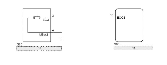
| *a | Combination Switch Assembly (ECO Mode Switch) |
| *b | Air Conditioning Amplifier Assembly |
PROCEDURE
-
READ VALUE USING GTS
-
Connect the GTS to the DLC3.
-
Turn the ignition switch to ON.
-
Turn the GTS on.
-
Enter the following menus: Body Electrical / Air Conditioner / Data List.
-
Check the values by referring to the table below.
Body Electrical > Air Conditioner > Data ListTester Display Measurement Item Range Normal Condition Diagnostic Note ECO Switch Combination switch assembly (ECO mode switch) OFF or ON OFF: Combination switch assembly (ECO mode switch) not operated
ON: Combination switch assembly (ECO mode switch) operated
-
Body Electrical > Air Conditioner > Data ListTester Display ECO Switch OK Combination switch assembly (ECO mode switch) condition displayed on the GTS changes with the actual switch operation. Result Proceed to OK NG
OK 
PROCEED TO NEXT SUSPECTED AREA SHOWN IN PROBLEM SYMPTOMS TABLE Click here
NG 
-
-
INSPECT COMBINATION SWITCH ASSEMBLY (ECO MODE SWITCH)
-
Remove the combination switch assembly (ECO mode switch).
-
Measure the resistance according to the value(s) in the table below.
Standard Resistance Tester Connection Condition Specified Condition 3 (ECU) - 4 (MSW2) Combination switch assembly (ECO mode switch) off (when switch is not pressed) 10 kΩ or higher 3 (ECU) - 4 (MSW2) Combination switch assembly (ECO mode switch) on (when switch is pressed) Below 1 Ω Result Proceed to OK NG
NG
REPLACE COMBINATION SWITCH ASSEMBLY (ECO MODE SWITCH) Click here
OK
-
-
CHECK HARNESS AND CONNECTOR (COMBINATION SWITCH ASSEMBLY [ECO MODE SWITCH] - AIR CONDITIONING AMPLIFIER ASSEMBLY)
-
Disconnect the G80 air conditioning amplifier assembly connector.
-
Disconnect the G60 combination switch assembly (ECO mode switch) connector.
-
Measure the resistance according to the value(s) in the table below.
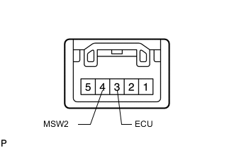
Standard Resistance Tester Connection Condition Specified Condition G80-18 (ECOS) - G60-3 (ECU) Always Below 1 Ω G80-18 (ECOS) - Body ground Always 10 kΩ or higher Result Proceed to OK NG
NG
REPAIR OR REPLACE HARNESS OR CONNECTOR
OK
-
-
CHECK HARNESS AND CONNECTOR (COMBINATION SWITCH ASSEMBLY [ECO MODE SWITCH] - BODY GROUND)
-
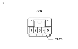
*a Front view of wire harness connector
(to Combination Switch Assembly [ECO Mode Switch])
Disconnect the combination switch assembly (ECO mode switch) connector.
-
Measure the resistance according to the value(s) in the table below.
Standard Resistance Tester Connection Condition Specified Condition G60-4 (MSW2) - Body ground Always Below 1 Ω Result Proceed to OK NG
OK
REPLACE AIR CONDITIONING AMPLIFIER ASSEMBLY Click here
NG
REPAIR OR REPLACE HARNESS OR CONNECTOR
-