AIR CONDITIONING SYSTEM(for Manual Air Conditioning System) Blower Motor Circuit
DESCRIPTION
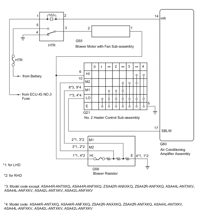
When the No. 2 heater control sub-assembly is operated, the heater relay will turn on to allow current to flow to the blower motor and then the motor will start rotating. Operating the No. 2 heater control sub-assembly switches the current flow between the blower resistor and body ground, thus, shifting the rotation speed of the blower motor with fan sub-assembly.
WIRING DIAGRAM
CAUTION / NOTICE / HINT
Note
Inspect the fuses for circuits related to this system before performing the following procedure.
PROCEDURE
-
INSPECT HTR RELAY
-
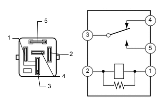
Remove the HTR relay from the No. 2 engine room relay block.
-
Measure the resistance according to the value(s) in the table below.
Standard Resistance Tester Connection Condition Specified Condition 3 - 5 Battery voltage is not applied between terminals 1 and 2 10 kΩ or higher 3 - 4 Battery voltage is applied between terminals 1 and 2 10 kΩ or higher 3 - 5 Battery voltage is applied between terminals 1 and 2 Below 1 Ω 3 - 4 Battery voltage is not applied between terminals 1 and 2 Below 1 Ω Result Proceed to OK NG
NG 
REPLACE HTR RELAY
OK 
-
-
INSPECT BLOWER MOTOR WITH FAN SUB-ASSEMBLY
-
Disconnect the G55 blower motor with fan sub-assembly connector.
-
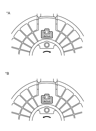
*A for LHD *B for RHD Connect a positive (+) lead from the battery to terminal 2 and negative (-) lead to terminal 1, and check that the motor operates.
OK The blower motor with fan sub-assembly operates smoothly. Result Proceed to OK NG
NG
REPLACE BLOWER MOTOR WITH FAN SUB-ASSEMBLY Click here
OK
-
-
INSPECT BLOWER RESISTOR
-
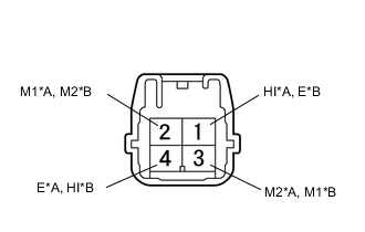
*A for LHD *B for RHD Remove the blower resistor.
-
Measure the resistance according to the value(s) in the table below.
Standard Resistance for LHD Tester Connection Condition Specified Condition 4 (E) - 1 (HI) Always 3.12 to 3.60 Ω 2 (M1) - 1 (HI) Always 1.45 to 1.67 Ω 3 (M2) - 1 (HI) Always 0.52 to 0.60 Ω for RHD Tester Connection Condition Specified Condition 1 (E) - 4 (HI) Always 3.12 to 3.60 Ω 3 (M1) - 4 (HI) Always 1.45 to 1.67 Ω 2 (M2) - 4 (HI) Always 0.52 to 0.60 Ω Result Proceed to OK NG
NG
REPLACE BLOWER RESISTOR Click here
OK
-
-
INSPECT NO. 2 HEATER CONTROL SUB-ASSEMBLY
-
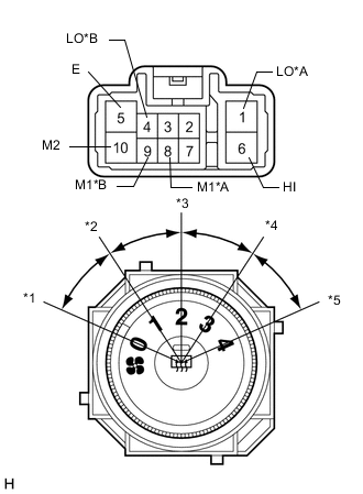
*A Model code except: ASA44R-ANTXKQ, ASA44R-ANFXKQ, ZSA42R-ANXXKQ, ZSA42R-ANFXKQ, ASA44L-ANTXKV, ASA44L-ANFXKV, ASA42L-ANTXKV, ASA42L-ANFXKV *B Model code: ASA44R-ANTXKQ, ASA44R-ANFXKQ, ZSA42R-ANXXKQ, ZSA42R-ANFXKQ, ASA44L-ANTXKV, ASA44L-ANFXKV, ASA42L-ANTXKV, ASA42L-ANFXKV *1 Blower Switch OFF Position *2 Blower Switch LO Position *3 Blower Switch M1 Position *4 Blower Switch M2 Position *5 Blower Switch HI Position Remove the No. 2 heater control sub-assembly.
-
Measure the resistance according to the value(s) in the table below.
Standard Resistance Model code except: ASA44R-ANTXKQ, ASA44R-ANFXKQ, ZSA42R-ANXXKQ, ZSA42R-ANFXKQ, ASA44L-ANTXKV, ASA44L-ANFXKV, ASA42L-ANTXKV, ASA42L-ANFXKV Tester Connection Switch Condition Specified Condition 1 (LO), 6 (HI), 8 (M1), 10 (M2) - 5 (E) Blower switch off 10 kΩ or higher 1 (LO) - 5 (E) Blower switch LO Below 1 Ω 1 (LO), 8 (M1) - 5 (E) Blower switch LO to M1 Below 1 Ω 1 (LO), 8 (M1) - 5 (E) Blower switch M1 Below 1 Ω 1 (LO), 8 (M1), 10 (M2) - 5 (E) Blower switch M1 to M2 Below 1 Ω 1 (LO), 10 (M2) - 5 (E) Blower switch M2 Below 1 Ω 1 (LO), 10 (M2), 6 (HI) - 5 (E) Blower switch M2 to HI Below 1 Ω 1 (LO), 6 (HI) - 5 (E) Blower switch HI Below 1 Ω Model code: ASA44R-ANTXKQ, ASA44R-ANFXKQ, ZSA42R-ANXXKQ, ZSA42R-ANFXKQ, ASA44L-ANTXKV, ASA44L-ANFXKV, ASA42L-ANTXKV, ASA42L-ANFXKV Tester Connection Switch Condition Specified Condition 4 (LO), 6 (HI), 9 (M1), 10 (M2) - 5 (E) Blower switch off 10 kΩ or higher 4 (LO) - 5 (E) Blower switch LO Below 1 Ω 4 (LO), 9 (M1) - 5 (E) Blower switch LO to M1 Below 1 Ω 4 (LO), 9 (M1) - 5 (E) Blower switch M1 Below 1 Ω 4 (LO), 9 (M1), 10 (M2) - 5 (E) Blower switch M1 to M2 Below 1 Ω 4 (LO), 10 (M2) - 5 (E) Blower switch M2 Below 1 Ω 4 (LO), 10 (M2), 6 (HI) - 5 (E) Blower switch M2 to HI Below 1 Ω 4 (LO), 6 (HI) - 5 (E) Blower switch HI Below 1 Ω Result Proceed to OK NG
NG
REPLACE NO. 2 HEATER CONTROL SUB-ASSEMBLY Click here
OK
-
-
CHECK HARNESS AND CONNECTOR (HTR RELAY - BATTERY AND BODY GROUND)
-
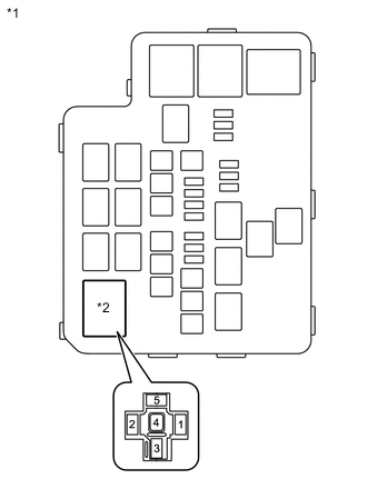
*1 No. 2 Engine Room Relay Block *2 HTR relay Remove the HTR relay from the No. 2 engine room relay block.
-
Measure the voltage according to the value(s) in the table below.
Standard Voltage Tester Connection Condition Specified Condition HTR relay terminal 1 - Body ground Ignition switch ON 11 to 14 V HTR relay terminal 5 - Body ground Always 11 to 14 V -
Measure the resistance according to the value(s) in the table below.
Standard Resistance Tester Connection Condition Specified Condition HTR relay terminal 4 - Body ground Always Below 1 Ω Result Proceed to OK NG
NG
REPAIR OR REPLACE HARNESS OR CONNECTOR
OK
-
-
CHECK HARNESS AND CONNECTOR (HTR RELAY - AIR CONDITIONING AMPLIFIER ASSEMBLY)
-
Remove the HTR relay from the No. 2 engine room relay block.
-
Disconnect the G80 air conditioning amplifier assembly connector.
-
Measure the resistance according to the value(s) in the table below.
Standard Resistance Tester Connection Condition Specified Condition HTR relay terminal 2 - G80-14 (HR) Always Below 1 Ω HTR relay terminal 2 - Body ground Always 10 kΩ or higher Result Proceed to OK NG
NG
REPAIR OR REPLACE HARNESS OR CONNECTOR
OK
-
-
CHECK HARNESS AND CONNECTOR (AIR CONDITIONING AMPLIFIER ASSEMBLY - NO. 2 HEATER CONTROL SUB-ASSEMBLY)
-
Disconnect the G80 air conditioning amplifier assembly connector.
-
Disconnect the G21 No. 2 heater control sub-assembly connector.
-
Measure the resistance according to the value(s) in the table below.
Standard Resistance Model code except: ASA44R-ANTXKQ, ASA44R-ANFXKQ, ZSA42R-ANXXKQ, ZSA42R-ANFXKQ, ASA44L-ANTXKV, ASA44L-ANFXKV, ASA42L-ANTXKV, ASA42L-ANFXKV Tester Connection Condition Specified Condition G80-17 (SBLW) - G21-1 (LO) Always Below 1 Ω G80-17 (SBLW) - Body ground Always 10 kΩ or higher Model code: ASA44R-ANTXKQ, ASA44R-ANFXKQ, ZSA42R-ANXXKQ, ZSA42R-ANFXKQ, ASA44L-ANTXKV, ASA44L-ANFXKV, ASA42L-ANTXKV, ASA42L-ANFXKV Tester Connection Condition Specified Condition G80-17 (SBLW) - G21-4 (LO) Always Below 1 Ω G80-17 (SBLW) - Body ground Always 10 kΩ or higher Result Proceed to OK NG
NG
REPAIR OR REPLACE HARNESS OR CONNECTOR
OK
-
-
CHECK HARNESS AND CONNECTOR (BLOWER RESISTOR - NO. 2 HEATER CONTROL SUB-ASSEMBLY AND BODY GROUND)
-
Disconnect the G56 blower resistor connector.
-
Disconnect the G21 No. 2 heater control sub-assembly connector.
-
Measure the resistance according to the value(s) in the table below.
Standard Resistance for LHD *1: Model code except: ASA44R-ANTXKQ, ASA44R-ANFXKQ, ZSA42R-ANXXKQ, ZSA42R-ANFXKQ, ASA44L-ANTXKV, ASA44L-ANFXKV, ASA42L-ANTXKV, ASA42L-ANFXKVTester Connection Condition Specified Condition G56-1 (HI) - G21-6 (HI) Always Below 1 Ω G56-3 (M2) - G21-10 (M2) Always Below 1 Ω G56-2 (M1) - G21-8 (M1)*1
G56-2 (M1) - G21-9 (M1)*2
Always Below 1 Ω G56-4 (E) - Body ground Always Below 1 Ω G21-5 (E) - Body ground Always Below 1 Ω G56-1 (HI) - Body ground Always 10 kΩ or higher G56-3 (M2) - Body ground Always 10 kΩ or higher G56-2 (M1) - Body ground Always 10 kΩ or higher
*2: Model code: ASA44R-ANTXKQ, ASA44R-ANFXKQ, ZSA42R-ANXXKQ, ZSA42R-ANFXKQ, ASA44L-ANTXKV, ASA44L-ANFXKV, ASA42L-ANTXKV, ASA42L-ANFXKV
for RHD *1: Model code except: ASA44R-ANTXKQ, ASA44R-ANFXKQ, ZSA42R-ANXXKQ, ZSA42R-ANFXKQ, ASA44L-ANTXKV, ASA44L-ANFXKV, ASA42L-ANTXKV, ASA42L-ANFXKVTester Connection Condition Specified Condition G56-4 (HI) - G21-6 (HI) Always Below 1 Ω G56-2 (M2) - G21-10 (M2) Always Below 1 Ω G56-3 (M1) - G21-8 (M1)*1
G56-3 (M1) - G21-9 (M1)*2
Always Below 1 Ω G56-1 (E) - Body ground Always Below 1 Ω G21-5 (E) - Body ground Always Below 1 Ω G56-4 (HI) - Body ground Always 10 kΩ or higher G56-2 (M2) - Body ground Always 10 kΩ or higher G56-3 (M1) - Body ground Always 10 kΩ or higher
*2: Model code: ASA44R-ANTXKQ, ASA44R-ANFXKQ, ZSA42R-ANXXKQ, ZSA42R-ANFXKQ, ASA44L-ANTXKV, ASA44L-ANFXKV, ASA42L-ANTXKV, ASA42L-ANFXKV
Result Proceed to OK NG
NG
REPAIR OR REPLACE HARNESS OR CONNECTOR
OK
-
-
CHECK HARNESS AND CONNECTOR (BLOWER MOTOR WITH FAN SUB-ASSEMBLY - NO. 2 HEATER CONTROL SUB-ASSEMBLY)
-
Disconnect the G55 blower motor with fan sub-assembly connector.
-
Disconnect the G21 No. 2 heater control sub-assembly connector.
-
Measure the resistance according to the value(s) in the table below.
Standard Resistance Tester Connection Condition Specified Condition G55-1 - G21-6 (HI) Always Below 1 Ω G55-1 - Body ground Always 10 kΩ or higher Result Proceed to OK NG
NG
REPAIR OR REPLACE HARNESS OR CONNECTOR
OK
-
-
CHECK HARNESS AND CONNECTOR (BLOWER MOTOR WITH FAN SUB-ASSEMBLY - HTR RELAY)
-
Disconnect the HTR relay connector.
-
Disconnect the G55 blower motor with fan sub-assembly connector.
-
Measure the resistance according to the value(s) in the table below.
Standard Resistance Tester Connection Condition Specified Condition HTR relay terminal 3 - G55-2 Always Below 1 Ω HTR relay terminal 3 - Body ground Always 10 kΩ or higher Result Proceed to OK NG
OK
PROCEED TO NEXT SUSPECTED AREA SHOWN IN PROBLEM SYMPTOMS TABLE Click here
NG
REPAIR OR REPLACE HARNESS OR CONNECTOR
-