AIR CONDITIONING SYSTEM(for Manual Air Conditioning System) Recirculation Damper Servo Motor Circuit
DESCRIPTION
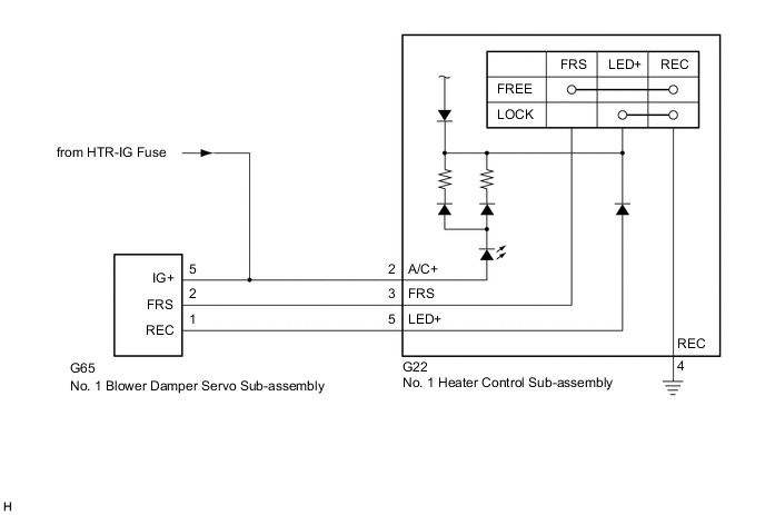
The No. 1 blower damper servo sub-assembly and No. 1 heater control sub-assembly are powered through the HTR-IG fuse. Operating the No. 1 heater control sub-assembly drives the the No. 1 blower damper servo sub-assembly to switch between fresh and recirculation mode.
WIRING DIAGRAM
CAUTION / NOTICE / HINT
Note
Inspect the fuses for circuits related to this system before performing the following procedure.
PROCEDURE
-
INSPECT NO. 1 BLOWER DAMPER SERVO SUB-ASSEMBLY
-
Remove the No. 1 blower damper servo sub-assembly.
-
Connect a positive (+) lead from the battery to terminal 5 (IG+) and negative (-) lead to terminal 2 (FRS), then check that the arm turns to the fresh side smoothly.
-
Connect a positive (+) lead from the battery to terminal 5 (IG+) and negative (-) lead to terminal 1 (REC), then check that the arm turns to the recirculation side smoothly.
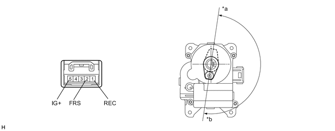
*a Recirculation Position *b Fresh Position Result Proceed to OK NG
NG 
REPLACE RECIRCULATION DAMPER SERVO SUB-ASSEMBLY Click here
OK 
-
-
INSPECT NO. 1 HEATER CONTROL SUB-ASSEMBLY
-
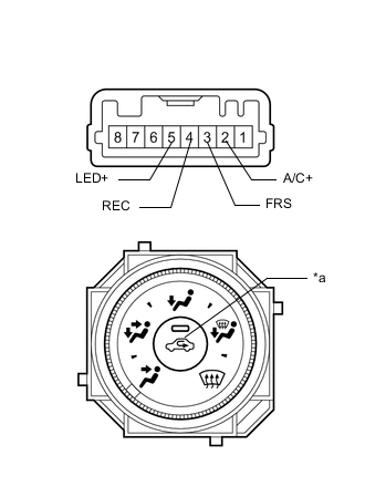
*a Recirculation/Fresh Switch Measure the resistance.
-
Remove the No. 1 heater control sub-assembly.
-
Measure the resistance according to the value(s) in the table below.
Standard Resistance Tester Connection Switch Condition Specified Condition 3 (FRS) - 4 (REC) Recirculation/fresh switch off Below 1 Ω 3 (FRS) - 4 (REC) Recirculation/fresh switch on 10 kΩ or higher 5 (LED+) - 4 (REC) Recirculation/fresh switch off 10 kΩ or higher 5 (LED+) - 4 (REC) Recirculation/fresh switch on Below 1 Ω
-
-
Check that the indicator light comes on.
-
Turn the recirculation/fresh switch to the on position.
-
Connect a positive (+) lead from the battery to terminal 2 (A/C+) and negative (-) lead to terminal 4 (REC), and check that the indicator light comes on.
OK The indicator light comes on.
Result Proceed to OK NG -
NG
REPLACE NO. 1 HEATER CONTROL SUB-ASSEMBLY Click here
OK
-
-
CHECK HARNESS AND CONNECTOR (NO. 1 BLOWER DAMPER SERVO SUB-ASSEMBLY - BATTERY)
-
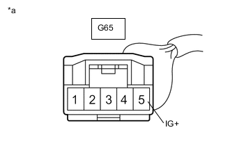
*a Front view of harness connector
(to No. 1 Blower Damper Servo Sub-assembly)
Disconnect the No. 1 blower damper servo sub-assembly connector.
-
Measure the voltage according to the value(s) in the table below.
Standard Voltage Tester Connection Switch Condition Specified Condition G65-5 (IG+) - Body ground Ignition switch off Below 1 V G65-5 (IG+) - Body ground Ignition switch ON 11 to 14 V Result Proceed to OK NG
NG
REPAIR OR REPLACE HARNESS OR CONNECTOR
OK
-
-
CHECK HARNESS AND CONNECTOR (NO. 1 HEATER CONTROL SUB-ASSEMBLY - BATTERY)
-
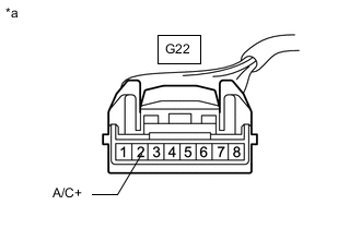
*a Front view of wire harness connector
(to No. 1 Heater Control Sub-assembly)
Disconnect the No. 1 heater control sub-assembly connector.
-
Measure the voltage according to the value(s) in the table below.
Standard Voltage Tester Connection Switch Condition Specified Condition G22-2 (A/C+) - Body ground Ignition switch off Below 1 V G22-2 (A/C+) - Body ground Ignition switch ON 11 to 14 V Result Proceed to OK NG
NG
REPAIR OR REPLACE HARNESS OR CONNECTOR
OK
-
-
CHECK HARNESS AND CONNECTOR (NO. 1 HEATER CONTROL SUB-ASSEMBLY - BODY GROUND)
-
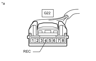
*a Front view of wire harness connector
(to No. 1 Heater Control Sub-assembly)
Disconnect the No. 1 heater control sub-assembly connector.
-
Measure the resistance according to the value(s) in the table below.
Standard Resistance Tester Connection Condition Specified Condition G22-4 (REC) - Body ground Always Below 1 Ω Result Proceed to OK NG
NG
REPAIR OR REPLACE HARNESS OR CONNECTOR
OK
-
-
CHECK HARNESS AND CONNECTOR (NO. 1 HEATER CONTROL SUB-ASSEMBLY - NO. 1 BLOWER DAMPER SERVO SUB-ASSEMBLY)
-
Disconnect the G22 No. 1 heater control sub-assembly connector.
-
Disconnect the G65 No. 1 blower damper servo sub-assembly connector.
-
Measure the resistance according to the value(s) in the table below.
Standard Resistance Tester Connection Condition Specified Condition G22-3 (FRS) - G65-2 (FRS) Always Below 1 Ω G22-5 (LED+) - G65-1 (REC) Always Below 1 Ω G22-3 (FRS) - Body ground Always 10 kΩ or higher G22-5 (LED+) - Body ground Always 10 kΩ or higher Result Proceed to OK NG
OK
PROCEED TO NEXT SUSPECTED AREA SHOWN IN PROBLEM SYMPTOMS TABLE Click here
NG
REPAIR OR REPLACE HARNESS OR CONNECTOR
-