AIR CONDITIONING SYSTEM(for Automatic Air Conditioning System), Diagnostic DTC:B1451/51
| DTC Code | DTC Name |
|---|---|
| B1451/51 | Compressor Solenoid Circuit |
DESCRIPTION
-
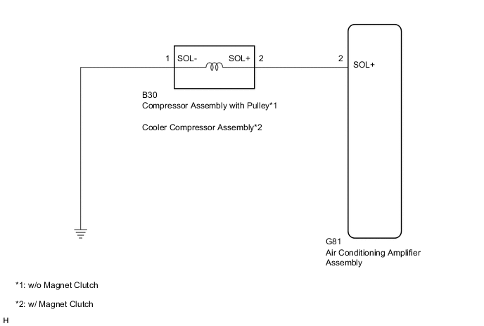
In this circuit, the compressor assembly with pulley*1 or cooler compressor assembly*2 receives a refrigerant compression demand signal from the air conditioning amplifier assembly.
Based on this signal, the compressor assembly with pulley*1 or cooler compressor assembly*2 changes the amount of compressor output.
-
*1: w/o Magnet Clutch
-
*2: w/ Magnet Clutch
-
| DTC No. | Detection Item | DTC Detection Condition | Trouble Area | Memory | Note |
|---|---|---|---|---|---|
| B1451/51 | Compressor Solenoid Circuit | Open or short in compressor solenoid circuit |
|
- | - |
Tech Tips
The air conditioning amplifier assembly stores the DTC of the respective malfunction if it has occurred for the period of time indicated in the brackets.
WIRING DIAGRAM
CAUTION / NOTICE / HINT
Note
When the battery is disconnected or the air conditioning amplifier assembly is replaced, be sure to perform servo motor initialization.
PROCEDURE
-
READ VALUE USING GTS
-
Connect the GTS to the DLC3.
-
Turn the ignition switch to ON.
-
Turn the GTS on.
-
Enter the following menus: Body Electrical / Air Conditioner / Data List.
-
Check the value(s) by referring to the table below.
Body Electrical > Air Conditioner > Data ListTester Display Measurement Item Range Normal Condition Diagnostic Note Regulator Control Current Solenoid valve control current Min.: 0 A
Max.: 0.997 A
Value changes between 0 A and 0.997 A in accordance with solenoid valve operation -
Body Electrical > Air Conditioner > Data ListTester Display Regulator Control Current OK The display is as specified in the normal condition column. Result Result Proceed to OK (When troubleshooting according to Problem Symptoms Table) A OK (When troubleshooting according to the DTC) B NG (w/o Magnet Clutch) C NG (w/ Magnet Clutch) D
A 
PROCEED TO NEXT SUSPECTED AREA SHOWN IN PROBLEM SYMPTOMS TABLE Click here
B
REPLACE AIR CONDITIONING AMPLIFIER ASSEMBLY Click here
D 
INSPECT COOLER COMPRESSOR ASSEMBLY Click here
C 
-
-
INSPECT COMPRESSOR ASSEMBLY WITH PULLEY
-
Remove the compressor assembly with pulley.
for 1AD-FTV, 2AD-FHV, 2AD-CCo, 2AD-DPF:
for 2AR-FE:
for 3ZR-FAE, 3ZR-FE:
-
Inspect the compressor assembly with pulley.
for 1AD-FTV, 2AD-FHV, 2AD-CCo, 2AD-DPF:
for 2AR-FE:
for 3ZR-FAE, 3ZR-FE:
Result Proceed to OK NG
NG
REPLACE COMPRESSOR ASSEMBLY WITH PULLEY for 1AD-FTV, 2AD-FHV, 2AD-CCo, 2AD-DPF: REPLACE COMPRESSOR ASSEMBLY WITH PULLEY Click here
REPLACE COMPRESSOR ASSEMBLY WITH PULLEY for 2AR-FE: REPLACE COMPRESSOR ASSEMBLY WITH PULLEY Click here
REPLACE COMPRESSOR ASSEMBLY WITH PULLEY for 3ZR-FAE, 3ZR-FE: REPLACE COMPRESSOR ASSEMBLY WITH PULLEY Click hereOK
-
-
CHECK HARNESS AND CONNECTOR (COMPRESSOR ASSEMBLY WITH PULLEY - BODY GROUND)
-
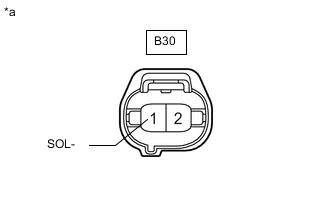
*a Front view of wire harness connector
(to Compressor Assembly with Pulley)
Disconnect the compressor assembly with pulley connector.
-
Measure the resistance according to the value(s) in the table below.
Standard Resistance Tester Connection Condition Specified Condition B30-1 (SOL-) - Body ground Always Below 1 Ω Result Proceed to OK NG
NG
REPAIR OR REPLACE HARNESS OR CONNECTOR
OK
-
-
CHECK HARNESS AND CONNECTOR (COMPRESSOR ASSEMBLY WITH PULLEY - AIR CONDITIONING AMPLIFIER ASSEMBLY)
-
Disconnect the G81 air conditioning amplifier assembly connector.
-
Disconnect the B30 compressor assembly with pulley connector.
-
Measure the resistance according to the value(s) in the table below.
Standard Resistance Tester Connection Condition Specified Condition G81-2 (SOL+) - B30-2 (SOL+) Always Below 1 Ω G81-2 (SOL+) - Body ground Always 10 kΩ or higher Result Result Proceed to OK (When troubleshooting according to Problem Symptoms Table) A OK (When troubleshooting according to the DTC) B NG C
A
PROCEED TO NEXT SUSPECTED AREA SHOWN IN PROBLEM SYMPTOMS TABLE Click here
B
REPLACE AIR CONDITIONING AMPLIFIER ASSEMBLY Click here
C
REPAIR OR REPLACE HARNESS OR CONNECTOR
-
-
INSPECT COOLER COMPRESSOR ASSEMBLY
-
Remove the cooler compressor assembly.
-
Inspect the cooler compressor assembly.
Result Proceed to OK NG
NG
REPLACE COOLER COMPRESSOR ASSEMBLY Click here
OK
-
-
CHECK HARNESS AND CONNECTOR (COOLER COMPRESSOR ASSEMBLY - BODY GROUND)
-
*a Front view of wire harness connector
(to Cooler Compressor Assembly)
Disconnect the cooler compressor assembly connector.
-
Measure the resistance according to the value(s) in the table below.
Standard Resistance Tester Connection Condition Specified Condition B30-1 (SOL-) - Body ground Always Below 1 Ω Result Proceed to OK NG
NG
REPAIR OR REPLACE HARNESS OR CONNECTOR
OK
-
-
CHECK HARNESS AND CONNECTOR (COOLER COMPRESSOR ASSEMBLY - AIR CONDITIONING AMPLIFIER ASSEMBLY)
-
Disconnect the G81 air conditioning amplifier assembly connector.
-
Disconnect the B30 cooler compressor assembly connector.
-
Measure the resistance according to the value(s) in the table below.
Standard Resistance Tester Connection Condition Specified Condition G81-2 (SOL+) - B30-2 (SOL+) Always Below 1 Ω G81-2 (SOL+) - Body ground Always 10 kΩ or higher Result Result Proceed to OK (When troubleshooting according to Problem Symptoms Table) A OK (When troubleshooting according to the DTC) B NG C
A
PROCEED TO NEXT SUSPECTED AREA SHOWN IN PROBLEM SYMPTOMS TABLE Click here
B
REPLACE AIR CONDITIONING AMPLIFIER ASSEMBLY Click here
C
REPAIR OR REPLACE HARNESS OR CONNECTOR
-