AIR CONDITIONING SYSTEM(for Automatic Air Conditioning System), Diagnostic DTC:B14A3
| DTC Code | DTC Name |
|---|---|
| B14A3 | Front Passenger Side Solar Sensor Short Circuit |
DESCRIPTION
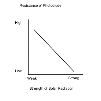
The automatic light control sensor is installed on the upper side of the instrument panel. It detects sunlight to control air conditioning AUTO mode. The output voltage from the automatic light control sensor varies in accordance with the amount of sunlight. When the sunlight increases, the output voltage increases. As the sunlight decreases, the output voltage decreases. The air conditioning amplifier assembly detects changes in the output voltage from the automatic light control sensor.
| DTC No. | Detection Item | DTC Detection Condition | Trouble Area | Memory | Note |
|---|---|---|---|---|---|
| B14A3 | Front Passenger Side Solar Sensor Short Circuit | Short in front passenger side automatic light control sensor circuit |
|
Memorized (4 seconds or more) | - |
Tech Tips
The air conditioning amplifier assembly stores the DTC of the respective malfunction if it has occurred for the period of time indicated in the brackets.
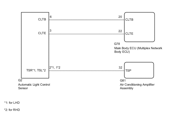
WIRING DIAGRAM
CAUTION / NOTICE / HINT
Note
-
When the battery is disconnected or the air conditioning amplifier assembly is replaced, be sure to perform servo motor initialization.
-
When replacing the main body ECU (multiplex network body ECU), make sure to replace it with a new one.
PROCEDURE
-
READ VALUE USING GTS
-
Connect the GTS to the DLC3.
-
Turn the ignition switch to ON.
-
Turn the GTS on.
-
Enter the following menus: Body Electrical / Air Conditioner / Data List.
-
Check the value(s) by referring to the table below.
Body Electrical > Air Conditioner > Data ListTester Display Measurement Item Range Normal Condition Diagnostic Note Solar Sensor (P Side) Front passenger side automatic light control sensor Min.: 0
Max.: 255
Front passenger side automatic light control sensor value increases as brightness increases -
Body Electrical > Air Conditioner > Data ListTester Display Solar Sensor (P Side) OK The display is as specified in the Normal Condition column. Result Result Proceed to OK (When troubleshooting according to Problem Symptoms Table) A OK (When troubleshooting according to the DTC) B NG C
A 
PROCEED TO NEXT SUSPECTED AREA SHOWN IN PROBLEM SYMPTOMS TABLE Click here
B
REPLACE AIR CONDITIONING AMPLIFIER ASSEMBLY Click here
C 
-
-
CHECK HARNESS AND CONNECTOR (POWER SOURCE CIRCUIT)
-
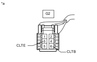
*a Front view of wire harness connector
(to Automatic Light Control Sensor)
Disconnect the automatic light control sensor connector.
-
Measure the voltage according to the value(s) in the table below.
Standard Voltage Tester Connection Switch Condition Specified Condition G2-6 (CLTB) - G2-3 (CLTE) Ignition switch off Below 1 V G2-6 (CLTB) - G2-3 (CLTE) Ignition switch ON 11 to 14 V Result Proceed to OK NG
NG 
CHECK HARNESS AND CONNECTOR (MAIN BODY ECU [MULTIPLEX NETWORK BODY ECU] - AUTOMATIC LIGHT CONTROL SENSOR) Click here
OK
-
-
CHECK HARNESS AND CONNECTOR (AUTOMATIC LIGHT CONTROL SENSOR - AIR CONDITIONING AMPLIFIER ASSEMBLY)
-
Disconnect the G81 air conditioning amplifier assembly connector.
-
Disconnect the G2 automatic light control sensor connector.
-
Measure the resistance according to the value(s) in the table below.
Standard Resistance for LHD Tester Connection Condition Specified Condition G81-32 (TSP) - G2-2 (TSR) Always Below 1 Ω G81-32 (TSP) - Body ground Always 10 kΩ or higher for RHD Tester Connection Condition Specified Condition G81-32 (TSP) - G2-1 (TSL) Always Below 1 Ω G81-32 (TSP) - Body ground Always 10 kΩ or higher Result Proceed to OK NG
NG
REPAIR OR REPLACE HARNESS OR CONNECTOR
OK
-
-
INSPECT AUTOMATIC LIGHT CONTROL SENSOR
-
Remove the automatic light control sensor with the connectors still connected.
-
Inspect the automatic light control sensor.
Result Proceed to OK NG
OK
REPLACE AIR CONDITIONING AMPLIFIER ASSEMBLY Click here
NG
REPLACE AUTOMATIC LIGHT CONTROL SENSOR Click here
-
-
CHECK HARNESS AND CONNECTOR (MAIN BODY ECU [MULTIPLEX NETWORK BODY ECU] - AUTOMATIC LIGHT CONTROL SENSOR)
-
Disconnect the G78 main body ECU (multiplex network body ECU) connector.
-
Disconnect G2 automatic light control sensor connector.
-
Measure the resistance according to the value(s) in the table below.
Standard Resistance Tester Connection Condition Specified Condition G78-20 (CLTB) - G2-6 (CLTB) Always Below 1 Ω G78-22 (CLTE) - G2-3 (CLTE) Always Below 1 Ω G78-20 (CLTB) - Body ground Always 10 kΩ or higher G78-22 (CLTE) - Body ground Always 10 kΩ or higher Result Proceed to OK NG
OK
REPLACE MAIN BODY ECU (MULTIPLEX NETWORK BODY ECU) for LHD: Click here for RHD: Click here
NG
REPAIR OR REPLACE HARNESS OR CONNECTOR
-