POWER BACK DOOR DRIVE UNIT INSTALLATION
CAUTION / NOTICE / HINT
PROCEDURE
-
INSTALL BACK DOOR DAMPER STAY LOWER BRACKET LH
-
Perform this procedure when replacing only the back door damper stay lower bracket LH.
-
Install the joint.
-
Set the protector cover to the joint.
-
Set the power back door unit assembly to the joint.
-
Using a 3 mm pin punch and hammer, tap a new pin into the joint.
-
Return the protecte cover to its original position and install the back door unit assembly set LH (spindle) to the back door damper stay lower bracket.
-
-
-
INSTALL BACK DOOR DAMPER STAY LOWER BRACKET RH
Tech Tips
Use the same procedure as for the LH side.
-
INSTALL POWER BACK DOOR UNIT ASSEMBLY SET RH
Tech Tips
Use the same procedure as for the LH side.
-
INSTALL POWER BACK DOOR UNIT ASSEMBLY SET LH
-
Install a new power back door unit assembly set LH.
Note
The spindle unit and bracket cannot be disassembled once they have been assembled. Therefore, when replacing the spindle, upper bracket or lower bracket, make sure to replace the spindle, upper bracket and lower bracket as a set.
-
When replacing the bolt with a new one:
-
Clean the threaded portion on the vehicle body with non-residue solvent.
-
-
When reusing the bolt:
-
Clean the threaded portion on the vehicle body with non-residue solvent.
-
Apply adhesive to the threads of the 4 bolts.
Adhesive Toyota Genuine Adhesive 1324, Three Bond 1324 or equivalent
-
-
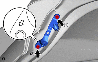
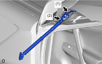
Temporarily install a new back door damper stay upper bracket LH.
-
Tighten the 2 bolts to install a new back door damper stay upper bracket LH.
Tech Tips
Tighten the bolts in the order shown in the illustration.
- Torque:
- 7.5 N*m { 76 kgf*cm, 66 in.*lbf }
-
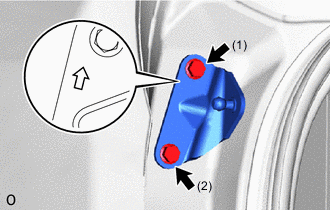
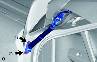
Temporarily install a new back door damper stay lower bracket LH.
-
Tighten the 2 bolts to install a new back door damper stay lower bracket LH.
Tech Tips
Tighten the bolts in the order shown in the illustration.
- Torque:
- 7.5 N*m { 76 kgf*cm, 66 in.*lbf }
-
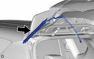
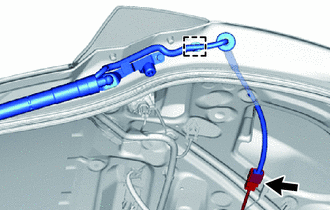
Install the power back door unit assembly set LH (spindle).
Note
-
Install the power back door unit assembly set LH while supporting the back door by hand.
-
Check that the power back door unit assembly set LH is engaged in the ball joint and that the back door unit assembly cannot be pulled out.
-
-
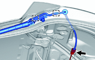
Connect the connector.
-
Attach the 2 clamps.
-
-
When reusing the power back door unit assembly set LH:
Note
The spindle unit and bracket cannot be disassembled once they have been assembled. Therefore, when replacing the spindle, upper bracket or lower bracket, make sure to replace the spindle, upper bracket and lower bracket as a set.
-
When replacing the bolt with a new one:
-
Clean the threaded portion on the vehicle body with non-residue solvent.
-
-
When reusing the bolt:
-
Clean the threaded portion on the vehicle body with non-residue solvent.
-
Apply adhesive to the threads of the 4 bolts.
Adhesive Toyota Genuine Adhesive 1324, Three Bond 1324 or equivalent
-
-
for Back Door Side:
-
Temporarily install the power back door unit assembly set LH (back door damper stay lower bracket LH).
-
Tighten the 2 bolts to install the power back door unit assembly set LH (back door damper stay lower bracket LH).
Tech Tips
Tighten the bolts in the order shown in the illustration.
- Torque:
- 7.5 N*m { 76 kgf*cm, 66 in.*lbf }
Note
-
Install the power back door unit assembly set LH while supporting the back door by hand.
-
Check that the power back door unit assembly set LH is engaged in the ball joint and that the back door unit assembly cannot be pulled out.
-
-
for Body Side:
-
Temporarily install the power back door unit assembly set LH (back door damper stay upper bracket LH).
-
Tighten the 2 bolts to install the power back door unit assembly set LH (back door damper stay upper bracket LH).
Tech Tips
Tighten the bolts in the order shown in the illustration.
- Torque:
- 7.5 N*m { 76 kgf*cm, 66 in.*lbf }
Note
-
Install the power back door unit assembly set LH while supporting the back door by hand.
-
Check that the power back door unit assembly set LH is engaged in the ball joint and that the back door unit assembly cannot be pulled out.
-
-
Connect the connector.
-
Attach the clamp and grommet.
-
-
-
INSTALL POWER BACK DOOR SENSOR ASSEMBLY LH
-
INSTALL POWER BACK DOOR SENSOR ASSEMBLY RH
Tech Tips
Use the same procedure as for the LH side.
-
INSTALL BACK DOOR TRIM BOARD ASSEMBLY
-
INSTALL BACK DOOR SIDE GARNISH LH
-
INSTALL BACK DOOR SIDE GARNISH RH
Tech Tips
Use the same procedure as for the LH side.
-
INSTALL BACK DOOR CENTER GARNISH