POWER BACK DOOR DRIVE UNIT REMOVAL
CAUTION / NOTICE / HINT
Note
The spindle unit and upper bracket cannot be disassembled once they have been assembled. Therefore, when replacing the spindle or upper bracket make sure to replace the spindle, upper bracket and lower bracket as a set.
PROCEDURE
-
REMOVE BACK DOOR CENTER GARNISH
-
REMOVE BACK DOOR SIDE GARNISH LH
-
REMOVE BACK DOOR SIDE GARNISH RH
Tech Tips
Use the same procedure described for the LH side.
-
REMOVE BACK DOOR TRIM BOARD ASSEMBLY
-
REMOVE POWER BACK DOOR SENSOR ASSEMBLY LH
-
REMOVE POWER BACK DOOR SENSOR ASSEMBLY RH
Tech Tips
Use the same procedure described for the LH side.
-
REMOVE POWER BACK DOOR UNIT ASSEMBLY SET LH
Note
The spindle unit and bracket cannot be disassembled once they have been assembled. Therefore, when replacing the spindle, upper bracket or lower bracket, make sure to replace the spindle, upper bracket and lower bracket as a set.
-
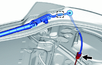
Disconnect the connector and detach the clamp and grommet.
-
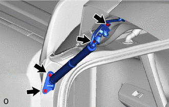
Remove the 4 bolts and power back door unit assembly set LH.
-
-
REMOVE POWER BACK DOOR UNIT ASSEMBLY SET RH
Tech Tips
Use the same procedure described for the LH side.
-
REMOVE BACK DOOR DAMPER STAY LOWER BRACKET LH
-
Perform this procedure when replacing only the back door damper stay lower bracket LH.
-
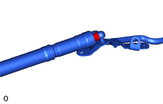
Move the protector cover until the pin can be seen.
-
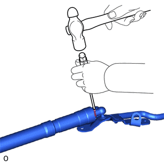
Using a 3 mm pin punch and hammer, tap out the pin from the joint.
-
Remove the joint and protector cover.
-
-
-
REMOVE BACK DOOR DAMPER STAY LOWER BRACKET RH
Tech Tips
Use the same procedure described for the LH side.