FRONT DOOR REASSEMBLY

CAUTION / NOTICE / HINT
Tech Tips
-
Use the same procedure for RHD and LHD vehicles.
-
The procedure listed below is for LHD vehicles.
-
Use the same procedure for the RH and LH sides.
-
The procedure listed below is for the LH side.
-
A bolt without a torque specification is shown in the standard bolt chart.
PROCEDURE
-
INSTALL FRONT DOOR PANEL CUSHION
-
Install 2 new front door panel cushions.
-
-
INSTALL FRONT DOOR LOWER OUTSIDE MOULDING SUB-ASSEMBLY LH
-
INSTALL NO. 1 BLACK OUT TAPE LH
-
INSTALL DOOR WINDOW FRAME MOULDING CLIP
-
INSTALL FRONT DOOR WINDOW REAR FRAME MOULDING LH
-
INSTALL DOOR FRAME GARNISH LH
-
Attach the clip to install a new door frame garnish LH.
-
-
INSTALL FRONT DOOR WEATHERSTRIP LH
-
Attach the 18 clips to install the front door weatherstrip LH.
-
Attach the 2 clips.
-
-
INSTALL FRONT DOOR CHECK ASSEMBLY LH
-
Apply MP grease to the sliding area of the front door check assembly LH.
-
When reusing a bolt labeled A:
-
Clean the threads of the bolt with non-residue solvent.
-
Apply adhesive to the threads of the bolt.
Adhesive Toyota Genuine Adhesive 1324, Three Bond 1324 or equivalent.
-
-
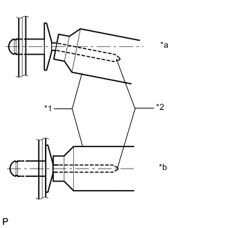
Install the front door check assembly to the door panel with the 2 bolts labeled B.
- Torque:
- 5.5 N*m { 56 kgf*cm, 49 in.*lbf }
-
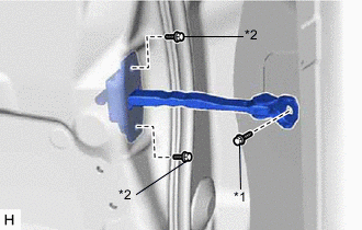
*1 Bolt A *2 Bolt B Install the front door check assembly to the body panel with the bolt labeled A.
- Torque:
- 30 N*m { 306 kgf*cm, 22 ft.*lbf }
-
-
INSTALL FRONT DOOR LOCK OPEN ROD LH
-
Install the front door lock open rod LH to the front door outside handle frame sub-assembly LH.
-
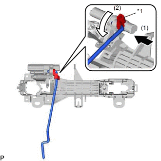
*1 Snap Rotate the snap in the direction indicated by the arrow shown in the illustration to attach the snap to the front door lock open rod LH.
-
-
INSTALL FRONT DOOR OUTSIDE HANDLE FRAME SUB-ASSEMBLY LH
-
Apply MP grease to the sliding area of the front door outside handle frame sub-assembly LH.
-
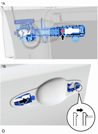
*A Inside *B Outside Using a T30 "TORX" socket wrench, attach the claw to install the front door outside handle frame sub-assembly LH with the screw.
- Torque:
- 4.0 N*m { 41 kgf*cm, 35 in.*lbf }
-
w/ Entry and Start System:
Attach the 3 clamps.
-
-
INSTALL FRONT DOOR FRONT OUTSIDE HANDLE PAD
-
Attach the 3 claws to install the front door front outside handle pad.
-
-
INSTALL FRONT DOOR REAR OUTSIDE HANDLE PAD
-
Attach the 2 claws to install the front door rear outside handle pad.
-
-
INSTALL FRONT DOOR OUTSIDE HANDLE ASSEMBLY LH
-
Apply MP grease to the sliding area of the front door outside handle assembly LH.
-
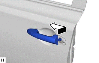
Install the front door outside handle assembly LH by moving it in the direction indicated by the arrow shown in the illustration.
-
w/ Entry and Start System:
-
Attach the claw of the connector to connect the connector.
-
Attach the 2 claws of the connector cover to connect the connector cover.
-
-
-
INSTALL FRONT DOOR INSIDE LOCKING CABLE ASSEMBLY LH
-
Install the front door inside locking cable assembly LH.
-
Attach the 3 claws to close the cover.
-
-
INSTALL FRONT DOOR LOCK REMOTE CONTROL CABLE ASSEMBLY LH
-
Install the front door lock remote control cable assembly LH.
-
-
INSTALL FRONT DOOR WITH MOTOR LOCK ASSEMBLY LH
-
INSTALL DOOR LOCK CYLINDER LH
-
Attach the 2 claws to install the door lock cylinder LH to the front door outside handle cover LH.
-
-
INSTALL FRONT DOOR OUTSIDE HANDLE COVER LH
-
Using a T30 "TORX" socket wrench, install the front door outside handle cover LH together with the front door lock cylinder with the screw.
- Torque:
- 4.0 N*m { 41 kgf*cm, 35 in.*lbf }
-
Install the hole plug.
-
-
INSTALL FRONT DOOR BELT MOULDING ASSEMBLY LH
-
INSTALL FRONT DOOR NO. 2 STIFFENER CUSHION
Tech Tips
When installing the front door No. 2 stiffener cushion, heat the front door panel using a heat light.
Standard Item Temperature Front Door Panel 40 to 60°C (104 to 140°F) Note
Do not heat the front door panel excessively.
-
Clean the front door panel surface.
-
Using a heat light, heat the front door panel surface.
-
Remove the double-sided tape from the front door panel.
-
Wipe off any tape adhesive residue with cleaner.
-
-
Install a new front door No. 2 stiffener cushion.
-
Using a heat light, heat the front door panel.
-
Remove the peeling paper from the face of the front door No. 2 stiffener cushion.
Tech Tips
After removing the peeling paper, keep the exposed adhesive free from foreign matter.
-
Install the front door No. 2 stiffener cushion with the 2 bolts.
Tech Tips
Press the front door No. 2 stiffener cushion firmly to install it.
- Torque:
- 6.2 N*m { 63 kgf*cm, 55 in.*lbf }
-
-
-
INSTALL FRONT DOOR REAR LOWER FRAME SUB-ASSEMBLY LH
-
Attach the guide to install the front door rear lower frame sub-assembly LH with the bolt.
- Torque:
- 6.2 N*m { 63 kgf*cm, 55 in.*lbf }
-
-
INSTALL POWER WINDOW REGULATOR MOTOR ASSEMBLY LH
-
INSTALL FRONT DOOR WINDOW REGULATOR SUB-ASSEMBLY LH
-
Apply MP grease to the sliding and rotating areas of the front door window regulator sub-assembly LH.
-
Temporarily install the temporary bolt to the front door window regulator sub-assembly LH.
-
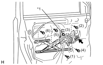
*1 Temporary Bolt Install the front door window regulator sub-assembly LH with the 5 bolts, and then tighten the temporary bolt.
Tech Tips
Tighten the bolts in the order shown in the illustration.
- Torque:
- 8.0 N*m { 82 kgf*cm, 71 in.*lbf }
Note
Be careful not to drop the front door window regulator as it may become damaged.
-
Connect the connector.
-
-
INSTALL FRONT DOOR GLASS RUN LH
-
Install the front door glass run LH.
-
-
INSTALL FRONT DOOR GLASS SUB-ASSEMBLY LH
-
Temporarily install the power window regulator master switch assembly with front door armrest base panel.
-
Connect the cable to the negative (-) battery terminal.
-
Operate the front door window regulator so that the front door glass can be installed.
-
Disconnect the negative (-) battery terminal.
Note
When disconnecting the cable, some systems need to be initialized after the cable is reconnected.
-
Remove the power window regulator master switch assembly with front door armrest base panel.
-
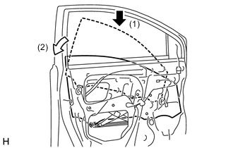
Insert the front door glass sub-assembly LH into the front door panel along the front door glass run LH as indicated by the arrows in the order shown in the illustration.
-
Install the front door glass sub-assembly LH with the 2 bolts.
- Torque:
- 8.0 N*m { 82 kgf*cm, 71 in.*lbf }
-
-
INSTALL FRONT DOOR SERVICE HOLE COVER LH
-
Apply new butyl tape to the front door panel.
-
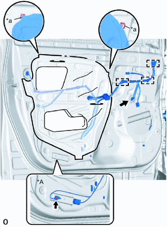
*A w/ Side Airbag Sensor *a Reference Point Pass the front door inside locking cable assembly LH, front door lock remote control cable assembly LH and wire harness through a new front door service hole cover LH, and then attach the front door service hole cover LH using the reference points on the front door panel.
Tech Tips
-
Securely install the front door service hole cover to prevent wrinkles and air bubbles.
-
There should be no wrinkles or folds after installing the front door service hole cover.
-
After installing the front door service hole cover, check the seal quality.
-
-
Connect the connector.
-
Attach the 3 clamps.
-
w/ Side Airbag Sensor:
Install the bolt to the wire harness.
- Torque:
- 8.4 N*m { 86 kgf*cm, 74 in.*lbf }
-
-
INSTALL FRONT NO. 1 SPEAKER ASSEMBLY (w/ Speaker)
-
INSTALL FRONT SPEAKER COVER (w/o Speaker)
-
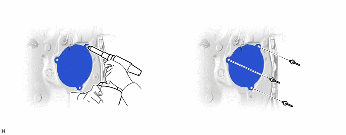
Install a nose piece to an air riveter or hand riveter.
-
Insert the mandrel part of a new rivet into the nose piece.
-
Insert the mandrel part of a new rivet into the nose piece.
-
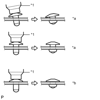
Using the riveter, install the front speaker cover with the 3 rivets as shown in the illustration.
Tech Tips
If the rivet cannot be cut, pull it once and cut it.
Note
-
*1 Riveter *2 Mandrel *a INCORRECT *b CORRECT Do not pry the rivet with the riveter as this will cause damage to the riveter and mandrel.
-
*1 Riveter *a INCORRECT *b CORRECT Confirm that the rivets are seated properly against the front speaker cover.
-
Do not tilt the riveter when installing the rivet to the front speaker cover.
-
Do not leave any space between the rivet head and front speaker cover.
-
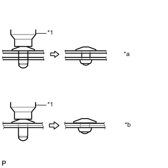
*1 Riveter *a INCORRECT *b CORRECT Do not leave any space between the front speaker cover and front door panel. Firmly hold together the 2 items while installing the rivet.
-
-
-
INSTALL DOOR SIDE AIRBAG SENSOR LH
-
INSTALL OUTER REAR VIEW MIRROR ASSEMBLY LH
-
INSTALL FRONT DOOR INNER GLASS WEATHERSTRIP LH
-
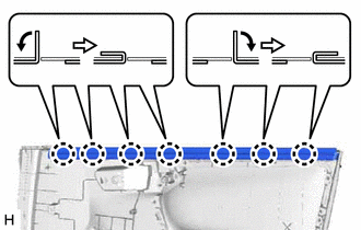
Install the front door inner glass weatherstrip LH to the front door trim board sub-assembly LH and fold down the 7 claws in the directions indicated by the arrows shown in the illustration.
-
-
INSTALL FRONT DOOR INSIDE HANDLE SUB-ASSEMBLY LH
-
Attach the 2 claws and guide to install the front door inside handle sub-assembly LH.
-
-
INSTALL FRONT DOOR TRIM BOARD SUB-ASSEMBLY LH
-
Connect the front door lock remote control cable assembly LH and front door inside locking cable assembly LH.
-
Engage the front door lock remote control cable assembly LH and front door inside locking cable assembly LH to the 2 clamps.
-
Attach the 9 clips to install the front door trim board sub-assembly LH.
-
Install the 3 screws.
-
-
INSTALL FRONT DOOR INSIDE HANDLE BEZEL PLUG LH
-
Attach the 3 claws to install the front door inside handle bezel plug LH.
-
-
INSTALL FRONT DOOR ASSIST GRIP COVER LH
-
Attach the guide, 2 clips and 4 claws to install the front door assist grip cover LH.
-
-
INSTALL POWER WINDOW REGULATOR MASTER SWITCH ASSEMBLY (for Driver Side)
-
INSTALL POWER WINDOW REGULATOR MASTER SWITCH ASSEMBLY WITH FRONT DOOR ARMREST BASE PANEL (for Driver Side)
-
Connect the connector.
-
Attach the 6 claws, 2 guides and 2 clips to install the power window regulator master switch assembly with front door armrest base panel.
-
-
INSTALL POWER WINDOW REGULATOR SWITCH ASSEMBLY (for Front Passenger Side)
-
INSTALL POWER WINDOW REGULATOR SWITCH ASSEMBLY WITH FRONT DOOR ARMREST BASE PANEL (for Front Passenger Side)
-
Connect the connector.
-
Attach the 6 claws, 2 guides and 2 clips to install the power window regulator switch assembly with front door armrest base panel.
-
-
INSTALL FRONT DOOR LOWER FRAME BRACKET GARNISH LH
-
Attach the 2 claws, 2 clips and 2 guides to install the front door lower frame bracket garnish.
-
-
CONNECT CABLE TO NEGATIVE BATTERY TERMINAL
Note
When disconnecting the cable, some systems need to be initialized after the cable is reconnected.
-
CHECK SRS WARNING LIGHT (w/ Side Airbag)
-
INITIALIZE POWER WINDOW CONTROL SYSTEM (w/ Jam Protection Function)
-
CHECK POWER WINDOW CONTROL SYSTEM
-
CHECK POWER DOOR LOCK CONTROL SYSTEM
-
CHECK OUTER REAR VIEW MIRROR