POWER BACK DOOR SYSTEM, Diagnostic DTC:B2220
| DTC Code | DTC Name |
|---|---|
| B2220 | Back Door Motor Circuit |
DESCRIPTION
This DTC is output when the multiplex network door ECU detects a malfunction in the motor built into the power back door unit assembly set LH or RH.
| DTC No. | Detection Item | DTC Detection Condition | Trouble Area |
|---|---|---|---|
| B2220 | Back Door Motor Circuit | Motor malfunction detected in power back door unit assembly set LH or RH |
|
WIRING DIAGRAM
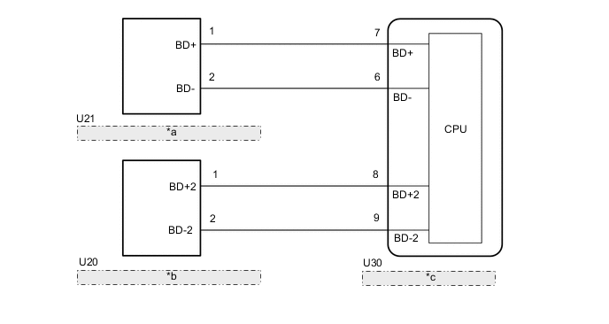
| *a | Power Back Door Unit Assembly Set LH |
| *b | Power Back Door Unit Assembly Set RH |
| *c | Multiplex Network Door ECU |
CAUTION / NOTICE / HINT
Note
If the replacement, removal and installation of the multiplex network door ECU or disconnection of the connectors of the multiplex network door ECU has been performed, initialize the power back door system.
PROCEDURE
-
CHECK FOR DTC
-
Clear the DTCs.
Body Electrical > Back Door > Clear DTCs -
Check for DTCs.
Body Electrical > Back Door > Trouble CodesResult Proceed to DTC B2220 is not output DTC B2220 is output
DTC B2220 is not output 
USE SIMULATION METHOD TO CHECK Click here
DTC B2220 is output 
-
-
INSPECT POWER BACK DOOR UNIT ASSEMBLY SET LH
-
Fully open the back door.
-
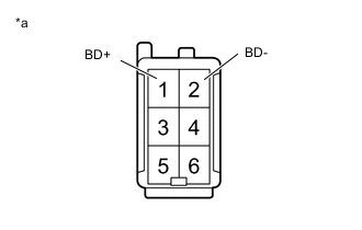
*a Component without harness connected
(Power Back Door Unit Assembly Set LH)
Disconnect the power back door unit assembly set LH connector.
-
Measure the resistance according to the value(s) in the table below.
Standard Resistance Tester Connection Condition Specified Condition 1 (BD+) - Body ground Always 10 kΩ or higher 2 (BD-) - Body ground Always 10 kΩ or higher 1 (BD+) - 2 (BD-) Always Below 1 MΩ Result Proceed to OK NG
NG
REPLACE POWER BACK DOOR UNIT ASSEMBLY SET LH Click here
OK
-
-
INSPECT POWER BACK DOOR UNIT ASSEMBLY SET RH
-
Fully open the back door.
-
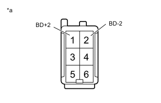
*a Component without harness connected
(Power Back Door Unit Assembly Set RH)
Disconnect the power back door unit assembly set RH connector.
-
Measure the resistance according to the value(s) in the table below.
Standard Resistance Tester Connection Condition Specified Condition 1 (BD+2) - Body ground Always 10 kΩ or higher 2 (BD-2) - Body ground Always 10 kΩ or higher 1 (BD+2) - 2 (BD-2) Always Below 1 MΩ Result Proceed to OK NG
NG
REPLACE POWER BACK DOOR UNIT ASSEMBLY SET RH Click here
OK
-
-
CHECK HARNESS AND CONNECTOR (MULTIPLEX NETWORK DOOR ECU - POWER BACK DOOR UNIT ASSEMBLY SET LH)
-
Disconnect the U30 multiplex network door ECU connector.
-
Disconnect the U21 power back door unit assembly set LH connector.
-
Measure the resistance according to the value(s) in the table below.
Standard Resistance Tester Connection Condition Specified Condition U30-7 (BD+) - U21-1 (BD+) Always Below 1 Ω U30-6 (BD-) - U21-2 (BD-) Always Below 1 Ω U30-7 (BD+) or U21-1 (BD+) - Body ground Always 10 kΩ or higher U30-6 (BD-) or U21-2 (BD-) - Body ground Always 10 kΩ or higher Result Proceed to OK NG
NG
REPAIR OR REPLACE HARNESS OR CONNECTOR
OK
-
-
CHECK HARNESS AND CONNECTOR (MULTIPLEX NETWORK DOOR ECU - POWER BACK DOOR UNIT ASSEMBLY SET RH)
-
Disconnect the U30 multiplex network door ECU connector.
-
Disconnect the U20 power back door unit assembly set RH connector.
-
Measure the resistance according to the value(s) in the table below.
Standard Resistance Tester Connection Condition Specified Condition U30-8 (BD+2) - U20-1 (BD+2) Always Below 1 Ω U30-9 (BD-2) - U20-2 (BD-2) Always Below 1 Ω U30-8 (BD+2) or U20-1 (BD+2) - Body ground Always 10 kΩ or higher U30-9 (BD-2) or U20-2 (BD-2) - Body ground Always 10 kΩ or higher Result Proceed to OK NG
OK
REPLACE MULTIPLEX NETWORK DOOR ECU Click here
NG
REPAIR OR REPLACE HARNESS OR CONNECTOR
-