POWER BACK DOOR SYSTEM TERMINALS OF ECU
-
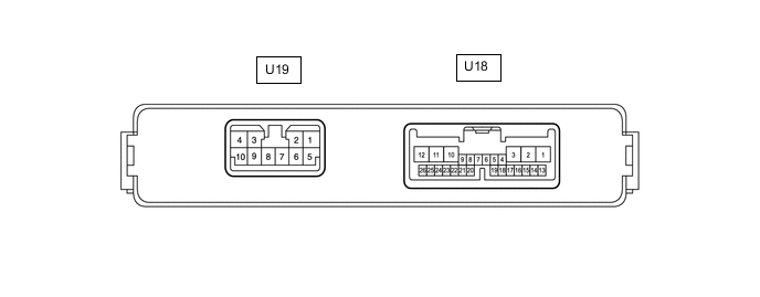
CHECK MULTIPLEX NETWORK DOOR ECU
-
Disconnect the U18 and U19 multiplex network door ECU connectors.
-
Measure the voltage and resistance according to the value(s) in the table below.
Terminal No. (Symbol) Wiring Color Terminal Description Condition Specified Condition U18-1 (ECUB) - Body ground W - Body ground Battery power supply Always 11 to 14 V U18-7 (IG) - Body ground W - Body ground IG power supply Ignition switch ON 11 to 14 V Ignition switch off Below 1 V U19-7 (GND) - Body ground W-B - Body ground Body ground Always Below 1 Ω U19-8 (B) - Body ground W - Body ground Battery power supply Always 11 to 14 V -
Reconnect the U18 and U19 multiplex network door ECU connectors.
-
Measure the voltage and waveform according to the value(s) in the table below.
Terminal No. (Symbol) Wiring Color Terminal Description Condition Specified Condition U18-2 (DSG2) - Body ground P - Body ground Power back door unit assembly set RH (door sensor) ground Always Below 1 V U18-3 (DSV2) - Body ground G - Body ground Power back door unit assembly set RH (door sensor) power supply Always 7 V or higher U18-5 (BZR+) - Body ground V - Body ground Wireless door lock buzzer signal Power back door warning buzzer sounding Pulse generation Power back door warning buzzer not sounding Below 1 V U18-6 (BDDN) - Body ground LG - Body ground Door control switch signal Door control switch on Below 1 V Door control switch off Pulse generation U18-11 (DSG) - Body ground P - Body ground Power back door unit assembly set LH (door sensor) ground Always Below 1 V U18-12 (DSV) - Body ground G - Body ground Power back door unit assembly set LH (door sensor) power supply Always 7 V or higher U18-16 (OSR) - U18-17 (OSE) SB - GR Power back door sensor assembly RH signal Power back door sensor assembly RH not pressed 4 to 6 V Power back door sensor assembly RH pressed Below 1 V U18-18 (OSL) - U18-17 (OSE) L - GR Power back door sensor assembly LH signal Power back door sensor assembly LH not pressed 4 to 6 V Power back door sensor assembly LH pressed Below 1 V U18-20 (MSW) - Body ground W - Body ground Power back door main switch signal Power back door main switch on Below 1 V Power back door main switch off Pulse generation U18-22 (DS2) - Body ground R - Body ground Power back door unit assembly set LH (door sensor) signal Power back door not operating 7 V or higher Power back door operating Pulse generation
(See waveform 2)
U18-23 (DS1) - Body ground L - Body ground Power back door unit assembly set LH (door sensor) signal Power back door not operating 7 V or higher Power back door operating Pulse generation
(See waveform 1)
U18-25 (DS22) - Body ground R - Body ground Power back door unit assembly set RH (door sensor) signal Power back door not operating 7 V or higher Power back door operating Pulse generation
(See waveform 2)
U18-26 (DS12) - Body ground L - Body ground Power back door unit assembly set RH (door sensor) signal Power back door not operating 7 V or higher Power back door operating Pulse generation
(See waveform 1)
U19-10 (DC+) - U19-9 (DC-) B - R Back door lock assembly (back door lock motor) circuit Back door lock motor operating 11 to 14 V
-
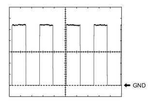
Using an oscilloscope, check waveform 1.
Waveform 1 (Reference) Item Condition Tester connection
-
U18-23 (DS1) - Body ground
-
U18-26 (DS12) - Body ground
Tool setting 2 V/DIV., 2 ms./DIV. Vehicle condition Power back door operating Tech Tips
The period changes in accordance to the speed at which the power back door is opened and closed.
-
-
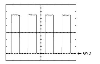
Using an oscilloscope, check waveform 2.
Waveform 2 (Reference) Item Condition Tester connection
-
U18-22 (DS2) - Body ground
-
U18-25 (DS22) - Body ground
Tool setting 2 V/DIV., 2 ms./DIV. Vehicle condition Power back door operating Tech Tips
The period changes in accordance to the speed at which the power back door is opened and closed.
-
-
-
-
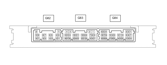
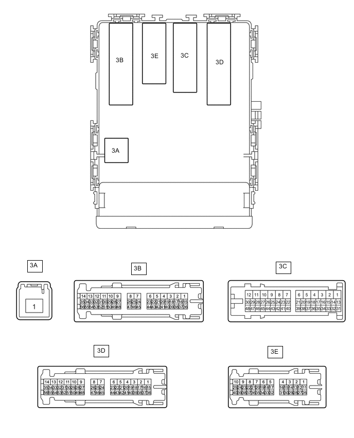
CHECK CERTIFICATION ECU (SMART KEY ECU ASSEMBLY) (w/ Entry and Start System)
-
Disconnect the G82 and G84 certification ECU (smart key ECU assembly) connectors.
-
Measure the voltage and resistance according to the value(s) in the table below.
Terminal No. (Symbol) Wiring Color Terminal Description Condition Specified Condition G82-2 (+B) - Body ground W - Body ground Battery power supply Always 11 to 14 V G82-10 (CUTB) - Body ground P - Body ground Battery power supply Always 11 to 14 V G84-5 (IG) - Body ground LG - Body ground IG power supply Ignition switch ON 11 to 14 V Ignition switch off Below 1 V G82-11 (E) - Body ground BR - Body ground Body ground Always Below 1 Ω -
Reconnect the G82 and G84 certification ECU (smart key ECU assembly) connectors.
-
Measure the voltage according to the value(s) in the table below.
Terminal No. (Symbol) Wiring Color Terminal Description Condition Specified Condition G83-27 (TSW5) - Body ground Y - Body ground Back door opener switch assembly signal Back door opener switch assembly off Pulse generation Back door opener switch assembly on Below 1 V
-
-
CHECK MAIN BODY ECU (MULTIPLEX NETWORK BODY ECU) AND INSTRUMENT PANEL JUNCTION BLOCK ASSEMBLY
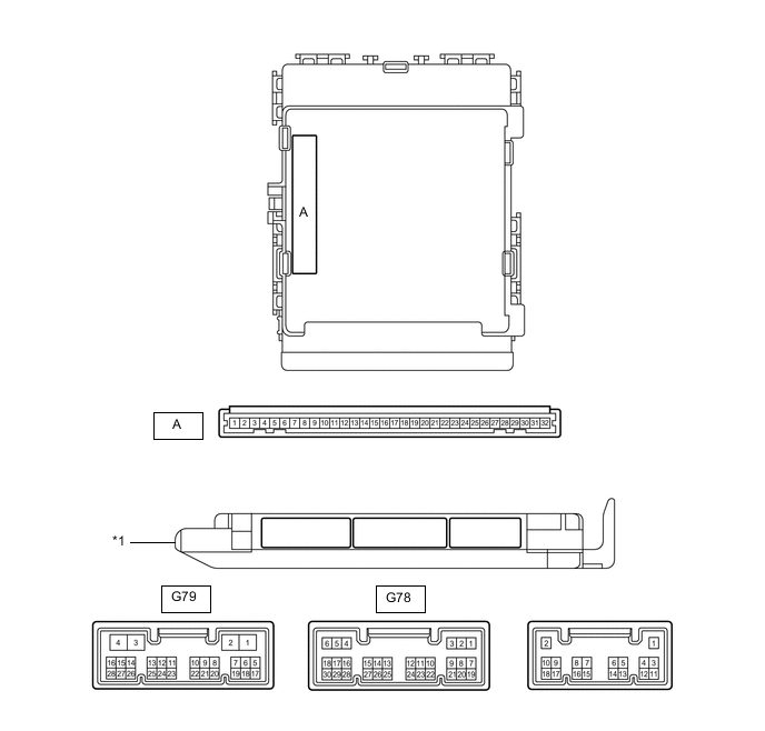
*1 Main Body ECU (Multiplex Network Body ECU) - -
-
Remove the main body ECU (multiplex network body ECU).
for LHD: Click here
for RHD: Click here
-
Connect the instrument panel junction block assembly connectors.
-
Measure the voltage and resistance according to the value(s) in the table below.
Terminal No. (Symbol) Wiring Color Terminal Description Condition Specified Condition A-30 (BECU) -Body ground None - Body ground Battery power supply Always 11 to 14 V A-29 (ACC) -Body ground None - Body ground ACC power supply Ignition switch ACC 11 to 14 V Ignition switch off Below 1 V A-32 (IG) - Body ground None - Body ground IG power supply Ignition switch ON 11 to 14 V Ignition switch off Below 1 V A-11 (GND1) - Body ground None - Body ground Body ground Always Below 1 Ω -
Install the main body ECU (multiplex network body ECU).
for LHD: Click here
for RHD: Click here
-
Measure the voltage according to the value(s) in the table below.
Terminal No. (Symbol) Wiring Color Terminal Description Condition Specified Condition G78-23 (BDSU) - Body ground* R - Body ground Back door opener switch assembly signal Back door opener switch assembly off Pulse generation Back door opener switch assembly on Below 1 V G79-27 (PBDS) - Body ground R - Body ground Back door control switch signal Back door control switch off Pulse generation Back door control switch on Below 1 V *: w/o Entry and Start System
-