WIPER AND WASHER SYSTEM(w/ Rain Sensor) Speed Signal Circuit
DESCRIPTION
The windshield wiper relay assembly receives a vehicle speed signal from the combination meter assembly to control the auto wiper system.
A voltage of 12 V or 5 V is output from the combination meter assembly and then input to the skid control ECU.
A voltage of 12 V or 5 V is output from each ECU or relay and then input to the combination meter assembly.
The signal is changed to a pulse signal at the transistor in the combination meter assembly.
Each ECU controls the respective system based on the pulse signal.
If a short occurs in any of the ECUs or in the wire harness connected to an ECU, all systems in the following diagram will not operate normally.
WIRING DIAGRAM
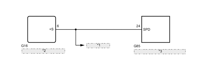
| *1 | to Related ECU |
| *2 | Combination Meter Assembly |
| *3 | Windshield Wiper Relay Assembly |
PROCEDURE
-
CHECK HARNESS AND CONNECTOR (WINDSHIELD WIPER RELAY ASSEMBLY - COMBINATION METER ASSEMBLY)
-
*1: for Radio Receiver Type
-
*2: for Navigation Receiver Type
-
*3: for Radio and Display Type
-
*4: w/ Automatic Headlight Beam Level Control System
-
*5: w/ Entry and Start System
-
*6: except Manual Transaxle
-
*7: Engine Type Diesel
-
*8: Engine Type Gasoline
-
Disconnect the G16 combination meter assembly connector.
-
Disconnect the G85 windshield wiper relay assembly connector.
-
Disconnect the G16 combination meter assembly connector.
-
Disconnect the G48 radio receiver assembly connector.*1
-
Disconnect the G139 navigation ECU sub-assembly connector.*2
-
Disconnect the G143 radio and display receiver assembly connector.*3
-
Disconnect the A67 headlight leveling ECU assembly connector.*4
-
Disconnect the G84 certification ECU (smart key ECU assembly) connector.*5
-
Disconnect the B79 TCM connector.*6
-
Disconnect the A61*7 or A62*8 ECM connector.
-
Measure the resistance according to the value(s) in the table below.
Standard Resistance Tester Connection Condition Specified Condition G85-24 (SPD) - G16-6 (+S) Always Below 1 Ω G85-24 (SPD) - Body ground Always 10 kΩ or higher Result Proceed to OK NG
NG 
REPAIR OR REPLACE HARNESS OR CONNECTOR
OK 
-
-
CHECK COMBINATION METER ASSEMBLY (OUTPUT WAVEFORM)
-
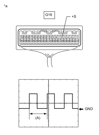
*a Component with harness connected
(Combination Meter Assembly)
Remove the combination meter assembly with the connector(s) still connected.
-
Connect an oscilloscope to terminal G16-6 (+S) and body ground.
-
Check the signal waveform according to the condition(s) in the table below.
Measurement Condition Item Condition Terminal No. (Symbol) G16-6 (+S) - Body ground Tool Setting 5 V/DIV., 20 ms./DIV. Condition Ignition switch ON, wheel being rotated OK The waveform is displayed as shown in the illustration. Tech Tips
When the system is functioning normally, one wheel revolution generates 4 pulses. As the vehicle speed increases, the width indicated by (A) in the illustration narrows.
Result Proceed to OK NG
OK
PROCEED TO NEXT SUSPECTED AREA SHOWN IN PROBLEM SYMPTOMS TABLE Click here
NG
GO TO METER / GAUGE SYSTEM Click here
-