WIPER AND WASHER SYSTEM(w/ Rain Sensor) Headlight Cleaner Motor and Relay Circuit
DESCRIPTION
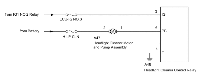
The headlight cleaner control relay controls the headlight cleaner motor and pump assembly.
WIRING DIAGRAM
CAUTION / NOTICE / HINT
Note
Inspect the fuses for circuits related to this system before performing the following inspection procedure.
PROCEDURE
-
INSPECT HEADLIGHT CLEANER MOTOR AND PUMP ASSEMBLY
-
Remove the headlight cleaner motor and pump assembly.
-
Inspect the headlight cleaner motor and pump assembly.
Result Proceed to OK NG
NG 
REPLACE HEADLIGHT CLEANER WASHER MOTOR AND PUMP ASSEMBLY Click here
OK 
-
-
CHECK HARNESS AND CONNECTOR (HEADLIGHT CLEANER MOTOR AND PUMP ASSEMBLY - HEADLIGHT CLEANER CONTROL RELAY AND BATTERY)
-
Disconnect the A47 headlight cleaner motor and pump assembly connector.
-
Disconnect the A48 headlight cleaner control relay connector.
-
Measure the resistance according to the value(s) in the table below.
Standard Resistance Tester Connection Condition Specified Condition A47-1 - A48-6 (PB) Always Below 1 Ω A47-1 - Body ground Always 10 kΩ or higher -
Measure the voltage according to the value(s) in the table below.
Standard Voltage Tester Connection Condition Specified Condition A47-2 - Body ground Always 11 to 14 V Result Proceed to OK NG
NG
REPAIR OR REPLACE HARNESS OR CONNECTOR
OK
-
-
CHECK HARNESS AND CONNECTOR (HEADLIGHT CLEANER CONTROL RELAY - BATTERY AND BODY GROUND)
-
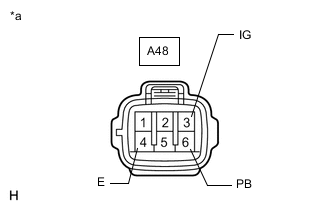
*a Front view of wire harness connector
(to Headlight Cleaner Control Relay)
Disconnect the headlight cleaner control relay connector.
-
Measure the resistance according to the value(s) in the table below.
Standard Resistance Tester Connection Condition Specified Condition A48-4 (E) - Body ground Always Below 1 Ω -
Measure the voltage according to the value(s) in the table below.
Standard Voltage Tester Connection Switch Condition Specified Condition A48-3 (IG) - Body ground Ignition switch ON 11 to 14 V Ignition switch off Below 1 V Result Proceed to OK NG
OK
PROCEED TO NEXT SUSPECTED AREA SHOWN IN PROBLEM SYMPTOMS TABLE Click here
NG
REPAIR OR REPLACE HARNESS OR CONNECTOR
-