WIPER AND WASHER SYSTEM(w/ Rain Sensor) Front Wiper Motor Circuit
DESCRIPTION
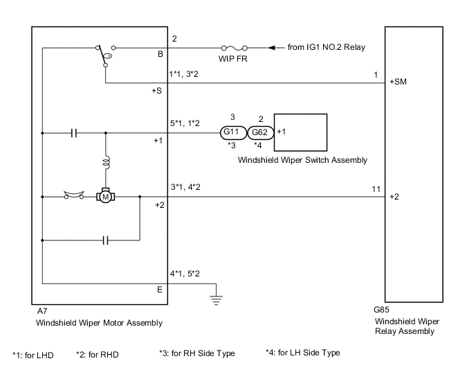
The windshield wiper relay assembly controls the windshield wiper motor assembly.
WIRING DIAGRAM
CAUTION / NOTICE / HINT
Note
Inspect the fuses for circuits related to this system before performing the following inspection procedure.
PROCEDURE
-
INSPECT WINDSHIELD WIPER MOTOR ASSEMBLY
-
Remove the windshield wiper motor assembly.
-
Inspect the windshield wiper motor assembly.
Result Proceed to OK NG
NG 
REPLACE WINDSHIELD WIPER MOTOR ASSEMBLY Click here
OK 
-
-
CHECK HARNESS AND CONNECTOR (WINDSHIELD WIPER MOTOR ASSEMBLY - BATTERY AND BODY GROUND)
-
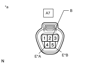
*A for LHD *B for RHD *a Front view of wire harness connector
(to Windshield Wiper Motor Assembly)
Disconnect the windshield wiper motor assembly connector.
-
Measure the resistance according to the value(s) in the table below.
Standard Resistance for LHD Tester Connection Condition Specified Condition A7-4 (E) - Body ground Always Below 1 Ω for RHD Tester Connection Condition Specified Condition A7-5 (E) - Body ground Always Below 1 Ω -
Measure the voltage according to the value(s) in the table below.
Standard Voltage Tester Connection Switch Condition Specified Condition A7-2 (B) - Body ground Ignition switch ON 11 to 14 V Ignition switch off Below 1 V Result Proceed to OK NG
NG
REPAIR OR REPLACE HARNESS OR CONNECTOR
OK
-
-
CHECK HARNESS AND CONNECTOR (WINDSHIELD WIPER MOTOR ASSEMBLY - WINDSHIELD WIPER RELAY ASSEMBLY)
-
Disconnect the A7 windshield wiper motor assembly connector.
-
Disconnect the G85 windshield wiper relay assembly connector.
-
Measure the resistance according to the value(s) in the table below.
Standard Resistance for LHD Tester Connection Condition Specified Condition A7-1 (+S) - G85-1 (+SM) Always Below 1 Ω A7-3 (+2) - G85-11 (+2) Always Below 1 Ω A7-1 (+S) - Body ground Always 10 kΩ or higher A7-3 (+2) - Body ground Always 10 kΩ or higher for RHD Tester Connection Condition Specified Condition A7-3 (+S) - G85-1 (+SM) Always Below 1 Ω A7-4 (+2) - G85-11 (+2) Always Below 1 Ω A7-3 (+S) - Body ground Always 10 kΩ or higher A7-4 (+2) - Body ground Always 10 kΩ or higher Result Proceed to OK NG
NG
REPAIR OR REPLACE HARNESS OR CONNECTOR
OK
-
-
CHECK HARNESS AND CONNECTOR (WINDSHIELD WIPER MOTOR ASSEMBLY - WINDSHIELD WIPER SWITCH ASSEMBLY)
-
Disconnect the A7 windshield wiper motor assembly connector.
-
Disconnect the G11*1 or G62*2 windshield wiper switch assembly connector.
-
*1: for RH Side Type
-
*2: for LH Side Type
-
-
Measure the resistance according to the value(s) in the table below.
Standard Resistance for LHD Tester Connection Condition Specified Condition A7-5 (+1) - G11-3 (+1) Always Below 1 Ω A7-5 (+1) - Body ground Always 10 kΩ or higher *1: for RH Side Typefor RHD Tester Connection Condition Specified Condition A7-1 (+1) - G11-3 (+1)*1 Always Below 1 Ω A7-1 (+1) - G62-2 (+1)*2 Always Below 1 Ω A7-1 (+1) - Body ground Always 10 kΩ or higher
*2: for LH Side Type
Result Proceed to OK NG
NG
REPAIR OR REPLACE HARNESS OR CONNECTOR
OK
-
-
REPLACE WINDSHIELD WIPER MOTOR ASSEMBLY
-
Temporarily replace the windshield wiper motor assembly with a new or normally functioning one.
Result Proceed to NEXT
NEXT
-
-
CHECK FRONT WIPER OPERATION
-
Check the front wiper operation.
Result Proceed to Front wiper operate normally Front wiper does not operate
Front wiper operate normally
END (WINDSHIELD WIPER MOTOR ASSEMBLY WAS DEFECTIVE)
Front wiper does not operate
PROCEED TO NEXT SUSPECTED AREA SHOWN IN PROBLEM SYMPTOMS TABLE Click here
-