WIPER AND WASHER SYSTEM(w/ Rain Sensor) Headlight Signal Circuit
DESCRIPTION
The headlight cleaner control relay detects the status of the low beam headlights.
WIRING DIAGRAM
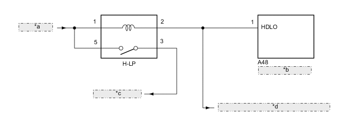
| *a | from Battery |
| *b | Headlight Cleaner Control Relay |
| *c | to Headlight Unit |
| *d | to Main Body ECU (Multiplex Network Body ECU) |
CAUTION / NOTICE / HINT
Note
First check that the low beam headlights operate normally.
PROCEDURE
-
CHECK HEADLIGHT CLEANER CONTROL RELAY
-
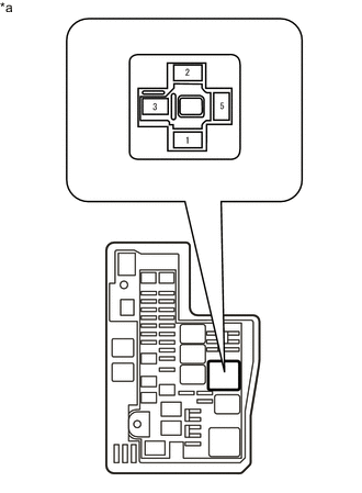
*a Front view of wire harness connector
(to Headlight Relay)
Remove the headlight relay from the No. 1 engine room relay block and junction block assembly.
-
Measure the voltage according to the value(s) in the table below.
Standard Voltage Tester Connection Condition Specified Condition Headlight relay terminal 2 - Body ground Light control switch in head position Below 1 V Light control switch off 11 to 14 V Result Proceed to OK NG
OK 
PROCEED TO NEXT SUSPECTED AREA SHOWN IN PROBLEM SYMPTOMS TABLE Click here
NG 
-
-
CHECK HARNESS AND CONNECTOR (HEADLIGHT RELAY [H-LP] - HEADLIGHT CLEANER CONTROL RELAY)
-
Remove the headlight relay from the No. 1 engine room relay block and junction block assembly.
-
Disconnect the A48 headlight cleaner control relay connector.
-
Measure the resistance according to the value(s) in the table below.
Standard Resistance Tester Connection Condition Specified Condition Headlight relay terminal 2 - A48-1 (HDLO) Always Below 1 Ω Headlight relay terminal 2 - Body ground Always 10 kΩ or higher Result Proceed to OK NG
OK
REPLACE HEADLIGHT CLEANER CONTROL RELAY Click here
NG
REPAIR OR REPLACE HARNESS OR CONNECTOR
-