LIGHTING SYSTEM Interior Light Circuit
DESCRIPTION
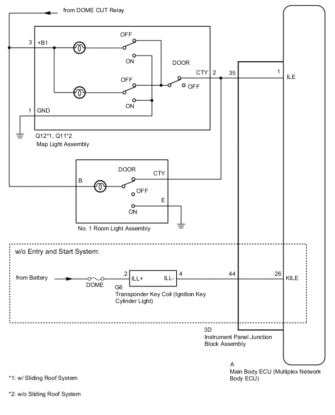
The main body ECU (multiplex network body ECU) controls the ignition key cylinder light (w/o Entry and Start System), map light and No. 1 room light.
WIRING DIAGRAM
CAUTION / NOTICE / HINT
Note
-
Inspect the fuses and bulbs for circuits related to this system before performing the following inspection procedure.
-
When replacing the main body ECU (multiplex network body ECU), make sure to replace it with a new one.
PROCEDURE
-
PERFORM ACTIVE TEST USING GTS (MAP LIGHT, NO. 1 ROOM LIGHT AND IGNITION KEY CYLINDER LIGHT)
-
Using the GTS, perform the Active Test.
Body Electrical > Main Body > Active TestTester Display Measurement Item Control Range Diagnostic Note Illuminated Entry System Map light, ignition key cylinder light (w/o Entry and Start System) and No. 1 room light ON or OFF Turn the map light switch and No. 1 room light switch to the DOOR position.
Body Electrical > Main Body > Active TestTester Display Illuminated Entry System Result Result Proceed to Map light assembly, No. 1 room light assembly and ignition key cylinder light comes on A Map light assembly and No. 1 room light assembly does not comes on B Map light assembly or No. 1 room light assembly does not comes on C Ignition key cylinder light does not comes on (w/o Entry and Start System) D
A 
PROCEED TO NEXT SUSPECTED AREA SHOWN IN PROBLEM SYMPTOMS TABLE Click here
C
PROCEED TO NEXT SUSPECTED AREA SHOWN IN PROBLEM SYMPTOMS TABLE Click here
D 
INSPECT TRANSPONDER KEY COIL (IGNITION KEY CYLINDER LIGHT) Click here
B 
-
-
INSPECT MAP LIGHT ASSEMBLY
-
Remove the map light assembly.
-
Inspect the map light assembly.
Result Proceed to OK NG
NG
REPLACE MAP LIGHT ASSEMBLY Click here
OK
-
-
CHECK HARNESS AND CONNECTOR (MAP LIGHT ASSEMBLY - BATTERY AND BODY GROUND)
-
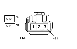
*A w/ Sliding Roof System *B w/o Sliding Roof System Disconnect the map light assembly connector.
-
Measure the voltage according to the value(s) in the table below.
Standard Voltage w/ Sliding Roof System Tester Connection Condition Specified Condition Q12-3 (+B1) - Body ground Battery saving control (interior light auto cut function) not operating 11 to 14 V w/o Sliding Roof System Tester Connection Condition Specified Condition Q11-3 (+B1) - Body ground Battery saving control (interior light auto cut function) not operating 11 to 14 V -
Measure the resistance according to the value(s) in the table below.
Standard Resistance w/ Sliding Roof System Tester Connection Condition Specified Condition Q12-1 (GND) - Body ground Always Below 1 Ω w/o Sliding Roof System Tester Connection Condition Specified Condition Q11-1 (GND) - Body ground Always Below 1 Ω Result Proceed to OK NG
NG
REPAIR OR REPLACE HARNESS OR CONNECTOR
OK
-
-
CHECK HARNESS AND CONNECTOR (MAP LIGHT ASSEMBLY - INSTRUMENT PANEL JUNCTION BLOCK ASSEMBLY)
-
Disconnect the Q12*1 or Q11*2 map light assembly connector.
*1: w/ Sliding Roof System
*2: w/o Sliding Roof System
-
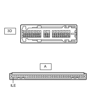
Disconnect the 3D instrument panel junction block assembly connector.
-
Measure the resistance according to the value(s) in the table below.
Standard Resistance w/ Sliding Roof System Tester Connection Condition Specified Condition Q12-2 (CTY) - 3D-35 Always Below 1 Ω Q12-2 (CTY) - Body ground Always 10 kΩ or higher w/o Sliding Roof System Tester Connection Condition Specified Condition Q11-2 (CTY) - 3D-35 Always Below 1 Ω Q11-2 (CTY) - Body ground Always 10 kΩ or higher Result Proceed to OK NG
NG
REPLACE INSTRUMENT PANEL JUNCTION BLOCK ASSEMBLY for LHD: REPLACE INSTRUMENT PANEL JUNCTION BLOCK ASSEMBLY Click here
REPLACE INSTRUMENT PANEL JUNCTION BLOCK ASSEMBLY for RHD: REPLACE INSTRUMENT PANEL JUNCTION BLOCK ASSEMBLY Click hereOK
-
-
INSPECT INSTRUMENT PANEL JUNCTION BLOCK ASSEMBLY
-
Remove the instrument panel junction block assembly.
for LHD:
for RHD:
-
Remove the main body ECU (multiplex network body ECU) from the instrument panel junction block assembly.
for LHD:
for RHD:
-
Measure the resistance according to the value(s) in the table below.
Standard Resistance Tester Connection Condition Specified Condition A-1 (ILE) - 3D-35 Always Below 1 Ω Result Proceed to OK NG
OK
REPLACE MAIN BODY ECU (MULTIPLEX NETWORK BODY ECU) for LHD: REPLACE MAIN BODY ECU (MULTIPLEX NETWORK BODY ECU) Click here
REPLACE MAIN BODY ECU (MULTIPLEX NETWORK BODY ECU) for RHD: REPLACE MAIN BODY ECU (MULTIPLEX NETWORK BODY ECU) Click hereNG
REPLACE INSTRUMENT PANEL JUNCTION BLOCK ASSEMBLY for LHD: REPLACE INSTRUMENT PANEL JUNCTION BLOCK ASSEMBLY Click here
REPLACE INSTRUMENT PANEL JUNCTION BLOCK ASSEMBLY for RHD: REPLACE INSTRUMENT PANEL JUNCTION BLOCK ASSEMBLY Click here -
-
INSPECT TRANSPONDER KEY COIL (IGNITION KEY CYLINDER LIGHT)
-
Remove the transponder key coil (ignition key cylinder light).
-
Inspect the transponder key coil (ignition key cylinder light).
Result Proceed to OK NG
NG
REPLACE TRANSPONDER KEY COIL (IGNITION KEY CYLINDER LIGHT) Click here
OK
-
-
CHECK HARNESS AND CONNECTOR (TRANSPONDER KEY COIL [IGNITION KEY CYLINDER LIGHT] - INSTRUMENT PANEL JUNCTION BLOCK ASSEMBLY AND BATTERY)
-
Disconnect the G6 transponder key coil (ignition key cylinder light) connector.
-
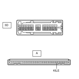
Disconnect the 3D instrument panel junction block assembly connector.
-
Measure the voltage according to the value(s) in the table below.
Standard Voltage Tester Connection Condition Specified Condition G6-2 (ILL+) - Body ground Always 11 to 14 V -
Measure the resistance according to the value(s) in the table below.
Standard Resistance Tester Connection Condition Specified Condition G6-4 (ILL-) - 3D-44 Always Below 1 Ω G6-4 (ILL-) - Body ground Always Below 1 Ω Result Proceed to OK NG
NG
REPAIR OR REPLACE HARNESS OR CONNECTOR
OK
-
-
INSPECT INSTRUMENT PANEL JUNCTION BLOCK ASSEMBLY
-
Remove the instrument panel junction block assembly.
for LHD:
for RHD:
-
Remove the main body ECU (multiplex network body ECU) from the instrument panel junction block assembly.
for LHD:
for RHD:
-
Measure the resistance according to the value(s) in the table below.
Standard Resistance Tester Connection Condition Specified Condition A-26 (KILE) - 3D-44 Always Below 1 Ω Result Proceed to OK NG
OK
REPLACE MAIN BODY ECU (MULTIPLEX NETWORK BODY ECU) for LHD: REPLACE MAIN BODY ECU (MULTIPLEX NETWORK BODY ECU) Click here
REPLACE MAIN BODY ECU (MULTIPLEX NETWORK BODY ECU) for RHD: REPLACE MAIN BODY ECU (MULTIPLEX NETWORK BODY ECU) Click hereNG
REPLACE INSTRUMENT PANEL JUNCTION BLOCK ASSEMBLY for LHD: REPLACE INSTRUMENT PANEL JUNCTION BLOCK ASSEMBLY Click here
REPLACE INSTRUMENT PANEL JUNCTION BLOCK ASSEMBLY for RHD: REPLACE INSTRUMENT PANEL JUNCTION BLOCK ASSEMBLY Click here -