LIGHTING SYSTEM Back Door Courtesy Switch Circuit
DESCRIPTION
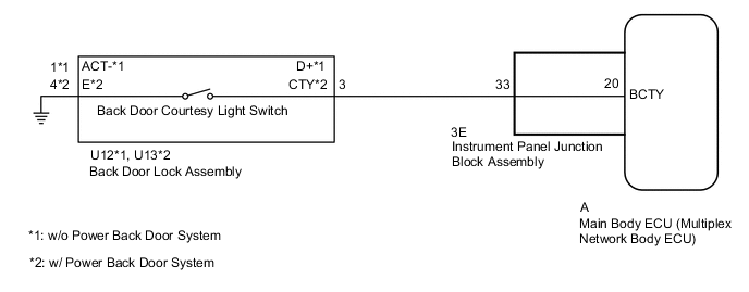
The main body ECU (multiplex network body ECU) receives a back door open or closed signal from back door courtesy light switch.
WIRING DIAGRAM
CAUTION / NOTICE / HINT
Note
When replacing the main body ECU (multiplex network body ECU), make sure to replace it with a new one.
PROCEDURE
-
READ VALUE USING GTS (BACK DOOR COURTESY LIGHT SWITCH)
-
Using the GTS, read the Data List.
Body Electrical > Main Body > Data ListTester Display Measurement Item Range Normal Condition Diagnostic Note Back Door Courtesy SW Back door courtesy light switch signal ON or OFF ON: Back door open
OFF: Back door closed
-
Body Electrical > Main Body > Data ListTester Display Back Door Courtesy SW OK The display is as specified in the normal condition column. Result Proceed to OK NG
OK 
PROCEED TO NEXT SUSPECTED AREA SHOWN IN PROBLEM SYMPTOMS TABLE Click here
NG 
-
-
INSPECT BACK DOOR LOCK ASSEMBLY
-
Remove the back door lock assembly.
-
Inspect the back door lock assembly.
Result Proceed to OK NG
NG
REPLACE BACK DOOR LOCK ASSEMBLY Click here
OK
-
-
CHECK HARNESS AND CONNECTOR (BACK DOOR LOCK ASSEMBLY - INSTRUMENT PANEL JUNCTION BLOCK ASSEMBLY AND BODY GROUND)
-
Disconnect the U12*1 or U13*2 back door lock assembly connector.
*1: w/o Power Back Door System
*2: w/ Power Back Door System
-
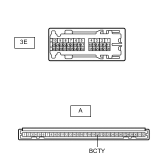
Disconnect the 3E instrument panel junction block assembly connector.
-
Measure the resistance according to the value(s) in the table below.
Standard Resistance w/o Power Back Door System Tester Connection Condition Specified Condition U12-3 (D+) - 3E-33 Always Below 1 Ω U12-1 (ACT-) - Body ground Always Below 1 Ω U12-3 (D+) - Body ground Always 10 kΩ or higher w/ Power Back Door System Tester Connection Condition Specified Condition U13-3 (CTY) - 3E-33 Always Below 1 Ω U13-4 (E) - Body ground Always Below 1 Ω U13-3 (CTY) - Body ground Always 10 kΩ or higher Result Proceed to OK NG
NG
REPAIR OR REPLACE HARNESS OR CONNECTOR
OK
-
-
INSPECT INSTRUMENT PANEL JUNCTION BLOCK ASSEMBLY
-
Remove the instrument panel junction block assembly.
for LHD:
for RHD:
-
Remove the main body ECU (multiplex network body ECU) from the instrument panel junction block assembly.
for LHD:
for RHD:
-
Measure the resistance according to the value(s) in the table below.
Standard Resistance Tester Connection Condition Specified Condition A-20 (BCTY) - 3E-33 Always Below 1 Ω Result Proceed to OK NG
OK
REPLACE MAIN BODY ECU (MULTIPLEX NETWORK BODY ECU) for LHD: REPLACE MAIN BODY ECU (MULTIPLEX NETWORK BODY ECU) Click here
REPLACE MAIN BODY ECU (MULTIPLEX NETWORK BODY ECU) for RHD: REPLACE MAIN BODY ECU (MULTIPLEX NETWORK BODY ECU) Click hereNG
REPLACE INSTRUMENT PANEL JUNCTION BLOCK ASSEMBLY for LHD: REPLACE INSTRUMENT PANEL JUNCTION BLOCK ASSEMBLY Click here
REPLACE INSTRUMENT PANEL JUNCTION BLOCK ASSEMBLY for RHD: REPLACE INSTRUMENT PANEL JUNCTION BLOCK ASSEMBLY Click here -